 Aim
Aim
Aim
Clickmap
Quick Guide
Design
ElectronicsSynchronization and data reduction are done in field programmable gate arrays, the XILINX chips. Each XILINX processes signals of those four detectors which are placed in succeeding z-positions within the same phi sector and generates from 32 inputs an 8-bit output at each H1 bunch crossing. The XILINX chips are reconfigurable by remote action; thus synchronization schemes, data reduction rules and logic output formats may be altered on demand and even be different in different phi sectors. For the sake of physics analysis a thorough bookkeeping of the changing configurations is mandatory. Therefore each configuration file is registered upon use and given a unique 16bit identifier. Finally 16 XILINXs will be operated; their configuration files taking approx. 64kByte.
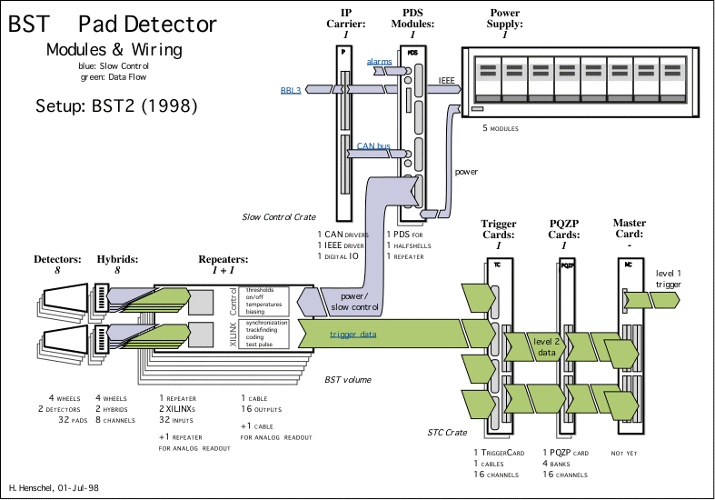
The BST Pad frontend electronics is linked to the trailer by two bunches of cables: one for Slow Control and Powering, the other for Trigger Control and Trigger Data. See the complete cabling layout.
Slow Control (including H1 alarms system)
Trigger LogicThe BST Store Card(s) and the TriggerCard(s) are read out when the Silicon Branch is included in the DAQ and two banks called TSCD and SITR are written. SITR is a record of the XILINX configuration identifier and the TriggerCard status register. TSCD contains for each event the full 2.3 microseconds history of the BST's digital channels, that is 16 Bytes per time slice with BST 1996 version, organized in four 32bit wide 'RAMs'. Look here for the complete channel map.
|
|
© by Hans Henschel, 14-sep-96, last revised: 05-nov-98
