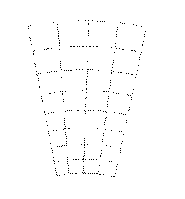
The layout of the pad detector shows 8 concentrical rings of four pads each which cover between 0.5 and 1.5 square centimeters. Each pad is a reverse biased diode read out through an oxide capacitor on top of it. Biasing of the diodes is made by the 'punchthrough' effect.
The readout capacitors are individually traced to the outer edge of the wafer where they are bonded to the amplifier/shaper chips.
|
|
© by Hans Henschel, 11-sep-96, last revised: 07-sep-98