 Under work. The principles (and simulation results) of the BST trigger
mask concept will be shown.
 Under work. The principles (and simulation results) of the BST trigger
mask concept will be shown.
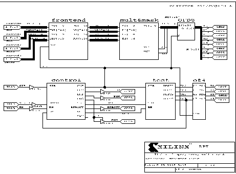
Here is an overview on the logic schemes implemented in the frontend configurable logic blocks:
Block scheme:
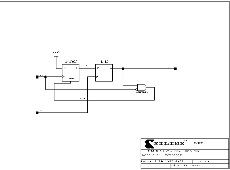
Input latch (subject of change):
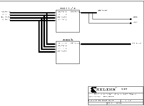
The multiplicity and masking blocks:
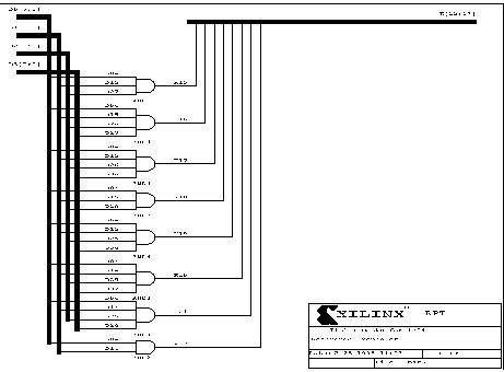
Mask submodules:
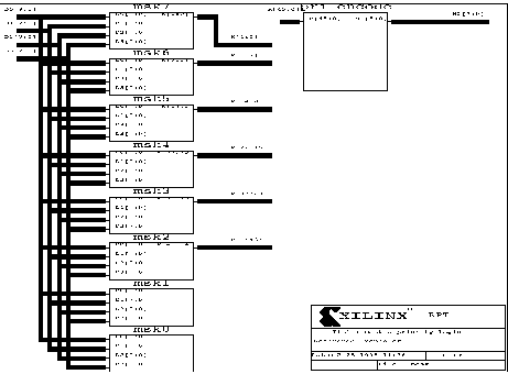
A mask example in detail:
An excerpt of the Technical Proposal:
To implement a lot of rarely used patterns rises the acceptance rate but on the other hand it increases the probability to trigger on particle background or even on electronics noise. Our simulation showed that a reasonable trade-off between physics efficiency and background rejection rate can hardly be settled at once prior to knowing the performance conditions. Fig. 8 illustrates the decision latitute: For a vertex uncertainty of ± 20cm about 54 masks are necessary to reach 100% efficiency. At this level, however, a certain amount of background events, e.g. 6% of beam wall interactions and 2% of beam gas interactions, will pass the trigger already. Note, that the scale of the diagram is given by the frequency of occurrence of a specified pattern in a generated event sample. Most of those masks are rarely frequented. The low number of masks and the independence of the 16 trigger blocks allows to implement the matching logics into a reconfigurable circuitry. Thus a suitable number of masks together with possible arbitrary patterns to cope with sensor faults or degradations due to radiation exposure can be generated and loaded for each and every performance condition.
The trigger sensors provide 32 diode signals each, which are amplified and discriminated by an integrated 4 channel chip currently being developed. Main emphasize will be payed to a short (45ns) peaking time despite a high capacitive input load [6]. The digital outputs of the four pads of every ring will be ORed together and transmitted in parallel to the trigger frontend logics, amounting to 512 channels in total for BST(1) and to 1024 for BST(2). Field programmable logic will synchronize the trigger signals to the common HERA machine clock and then check the hit patterns against a set of up to about 60 predefined masks. Additionally an adjustable multiplicity cut can be invoked. Simulation showed that for just 4 consecutive planes those three tasks easily fit into a single XILINX LCA series 3000 chip per phi sector. It is foreseen to add an extension input to every mask which will allow to link valid tracks of the first four planes to those of the second four in the fully equipped BST(2). Independent trigger decisions of any sectors are then ORed to a common level 1 trigger output, and as an option every sector may store its hit pattern in a pipeline for use by the central trigger logics at level 2, see fig. 12. Due to its fully parallel design this trigger is deadtime free and leaves plenty of time for combination with other triggers in the H1 central trigger circuitry. Obviously a sensor bias supply and test pulse circuitry will be incorporated.
|
|
© by Hans Henschel, 10-sep-96, last revised: 25-sep-98