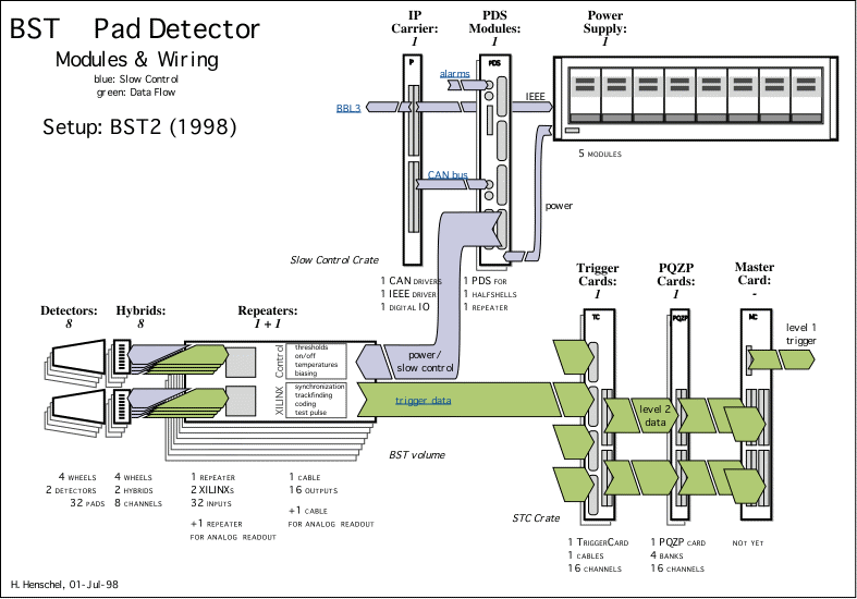
BST Pad Detector • Data Flow Primer
Besides the BST strip detector being used and continously upgraded
throughout the past years there is a silicon pad detector proposed (and
partly installed yet) with the aim to trigger in the BST sensitive region
beyond 176 degrees or to reject background respectively.
The silicon sensors for this type of detector have the same wedge-shaped
outline as the strip detectors (covering 22.5 degrees in phi) but only 32
sensitive areas, so-called pads, arranged in 8 concentrical rings. Sixteen
sensors form a wheel (or disk), four wheels are placed along z. Thus the
total channel count for these trigger detectors amounts to:
| 4
16
8
4 |
discs
sensors per disk
rings per sensor
pads per ring |
times
times
times
add up to |
| total: | 2048 | channels. |
Since the number of cables between the innermost detector region and the
trailer was heavily restricted we introduced several stages of data
reduction and 'preprocessing' while keeping the deadtime below the trigger
level 1 limit.
Overview:

- Amplification and shaping is done in a 4-channel ASIC developed by one of our engineers
together with others at CERN (a VIKING derivative). It has a peaking time
of 46ns.
- Digitization is done by a simple threshold dicriminator where a
threshold is common to all four pads of one ring.
- The four digital signals of one detector ring are then ORed
logically, introducing a data reduction of 4:1 by reducing the resolution
in phi to 1/16 of the full circle. There was considerable simulation
effort to show that the given coarse resolution does not essentially
affect the trigger effiency - see DESY preprint 93-002
and H1 note 04/92-221.
The stages 1 to 3 are implemented in the same ASIC, housing four analog
inputs and one digital output. Eight of these ASICs are placed on the same
hybrid to which the silicon sensor is
attached, that is within the detector active volume. The resulting 512
digital signals are transmitted directly to the repeater card, an electronics printed
circuit board placed some 10 centimeters behind the detector, yet still
inside the H1 Tracker.
There the signals are grouped 'sector-wise', that is: signals generated in
the same phi sector, although of different disks, are fed into one field
programmable gate array (XILINX), in total 32 per sector resulting in
16
gate arrays. These XILINXs contain synchronization, track finding and further
data reduction schemes which are reconfigurable on demand, e.g. to
implement either pointing vertex trigger or beam background rejection
function.
- All 32 parallel digital signals are first synchronized to the HERA
clock, either by simple latch or by sophisticated edge sensing circuitry.
(Schemes to reject extensive signal ringing have also been tested...)
Thereafter a 'hit' is represented by a logic 1 being stable for one HERA
clock cyle (96 ns), thereby dead time-free!
- This synchronous input pattern is compared to a set of predefined
'masks' in the manner of a lookup table to select valid 'tracks'. Note
that namely the mask set can be reprogrammed within wide limits allowing a
variety of (pre-)trigger conditions. The proposal describes a pointing
vertex trigger with built-in high-multiplicity veto...
- In order to further reduce the amount of signal lines to the trailer
the pattern check result has to be coded. Monte Carlo simulations showed
that around 50 different mask patterns are sufficient for the trigger aim
proposed. Thus an eight-bit trigger output word per sector is generated in
the XILINX. It will contain a 6 bit coded mask mask number (1 out of 64)
and additional two qualifier bits concerning the occupancy of the given
sector...
Stages 4 to 6 are implemented in a single XILINX per sector which
processes 32 asynchronous discriminated inputs and provides 8 synchronized
outputs to the BST trigger master logic.
- Trigger words from all sectors are combined in a set of lookup tables
and/or gate arrays in the BST trigger master logic, located on VME boards in the
trailer (silicon STC crate). This 'Master Card' will provide an 8bit
trigger word to the Level 1 Central Trigger Logic.
Bypassing the Central Trigger all output of the frontend data processing
(stages 4 to 6) is presented to the H1 pipelined data logging system PQZP. Here, upon a validated trigger the last
24 cycles of history are recorded to the TSCD bank.
© by Hans Henschel, 23-feb-98, last revised:
06-oct-98

