[Index] [Back] [Next]
7. SiDAQ Silicon Readout Data Acquisition
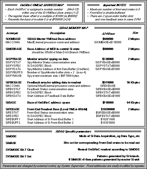
The protocols for the SiDAQ have been written largely application-specific, as compared to that of the parent VMEXI_SSP which was developed for more general purposes. Many of the base addresses for the Silicon Readout are assumed fixed but, by extensive use of relative offsets, their number is minimal and they are easily changed via equates. The principle ones are tabulated in Figure 8, together with the essential points and parameters which are of relevance to driving the readout as an integrated branch of a larger system.

Figure 8 : SiDAQ Memory Map Overview and Essentials
Basically the configuration assumed is compatible to that of Figure 6 where several front-end crates are coordinated around a VMEtaxi ringlet which is then integrated into a larger XIDAQ main central data acquisition ring. The master Silicon Readout VMEtaxi is assumed to be in the same crate as the slave branch VMEtaxi of the central DAQ. It therefore runs as a standard MEB unit (see VMEXI_SSP) providing its data from the source front-end crates equipped with OnSiRoC readout controllers. In addition it can be switched to generate patterns, as a test branch, either from just the master or built from the front-end slaves according to the SiMASK settings. The MEB itself is assumed to be the XRAM of the slave DAQ Branch VMEtaxi.
7.1. SiDAQ Communication Format
Much of the communication mapping is similar to that of the MEB/FEB mechanisms of XIDAQ. The front-end coordination protocol is relatively simple with the following communication offsets in addition to the data buffering:
-
SIFESTAT communication protocol.
$00 : SYSMODE
$04 : RUNNUM
$08 : TRIGGER1
$0C : TRIGGER2
$10 : XIMASK
$14 : Reserved
$18 : Number of buffers SINBUFFS. This acts as the run_prepare acknowledge!
$1C : Max Bytes per buffer SIMAXBYTES
$20 : Si-XIDAQ branch number
$24 : Reserved
$28 : Address of 1st buffer
$2C : Reserved
$30 : FEBMASK
$34 : DAQMODE
$38 : SIBITPAT of OnSiRoCs
$3C : Used to store the front-end unit number
Then follows the Event indicator area.
$40 : Event Number in Front-end Buffer 0
$44 : SIROERROR Readout error code for event in Front-end buffer 0
$48 : Si_nbytes Total number of bytes, Event in Buffer 0
$4C : Reserved
$50 : Event Number in Front-end Buffer 1
$54 : SIROERROR Readout error code for event in Front-end buffer 1
$58 : Si_nbytes Total number of bytes, Event in Buffer 1
$5C : Reserved
$60-$7C : Reserved for possible future buffering use
NOTE Si_nbytes is last to be set by front_end units when data are ready
Then the SiDAQSPEC array
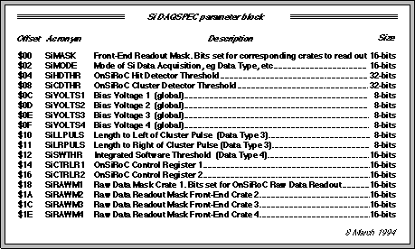
$80-$9C : Si DAQSPEC block. See Figure 9
When master finds an event ready from all front-end units it places information in a local store SIEVRDY of format:
$00 : Address of event data in 1st SIMASK fe crate as seen by that taxi
$04 : SIROERROR Readout error code for event in 1st SIMASK fe crate
$08 : Si_nbytes, Total number of bytes for event in 1st SIMASK fe crate
$0C : Buffer number of event data in 1st SIMASK fe crate
$n0 : Address of event data in SIMASK fe crate n+1 as seen by that taxi
$n4 : SIROERROR Readout error code for event in SIMASK fe crate n+1
$n8 : Si_nbytes, Total number of bytes for event in SIMASK fe crate n+1
$nC : Buffer number of event data in SIMASK fe crate n+1
Maximum number of front-end crates is limited by size of SIEVRDY (SIFEMAX)
After building, all of the Event indicator areas are zeroed by the master
with Si_nbytes as the last word to be cleared in each case
NOTE : An empty event must always have some bytes in it, eg a BOS head !
Feedback data are added to an event if the first location of the feedback data area, SIFBKDATA, is none-zero (ie equals the length in bytes)
This location is then re-zeroed at the end of the procedure.
The format of the feedback communication protocol at SIFBKSTAT is similar to that at SISPYSTAT except for the Event Indicator area.
For spy-monitoring, events are copied to the module at SISPYBASE:
-
1st buffer begins SISPYDATA. Maximum size of an event is SISPYMAXB
Format of monitoring memory Protocol starting at SISPYSTAT is:
$00 : SYSMODE
$04 : RUNNUM
$08 : TRIGGER1
$0C : TRIGGER2
$10 : XIMASK
$14 : Reserved
$18 : Number of event buffer slots SISPYBUFFS
$1C : Maximum Bytes per buffer slot SISPYMAXB
$20 : BUFF_ACTIVE 4 bytes indicating whether a cpu-task is using an evt slot
$24 : Reserved
$28 : Address of 1st buffer as seen by VMEtaxi Si master
$2C : Reserved
$30 : FEBMASK
$34 : DAQMODE
$38 : Not used
$3C : Not used
Then the Full Si Event Indicator area
$40 : Si Event Number in Si Buffer slot 0
$44 : Si Readout error code for event in Si Buffer slot 0
$48 : Total number of bytes, Event in Si Buffer slot 0
$4C : Reserved
$50 : Si Event Number in Si Buffer slot 1
$54 : Si Readout error code for event in Si Buffer slot 1
$58 : Total number of bytes, Event in Si Buffer slot 1
$5C : Reserved
$60 : Si Event Number in Si Buffer slot 2
$64 : Si Readout error code for event in Si Buffer slot 2
$68 : Total number of bytes, Event in Si Buffer slot 2
$6C : Reserved
$70 : Si Event Number in Si Buffer slot 3
$74 : Si Readout error code for event in Si Buffer slot 3
$78 : Total number of bytes, Event in Si Buffer slot 3
$7C : Reserved
Then the SiDAQSPEC array
$80-$9C : Si DAQSPEC block. See Figure 9
Routine on taxi side only needs to toggle with Si Event Indicator area
As with Si Front-End protocol, the tnbytes is used as the ready indicator
BUFF_ACTIVE word is for toggling via SiUser calls
When a particular monitoring unit has finished with an event it
1) clears relevant event indicator area, with tnbytes LAST !
2) then clears corresponding BUFF_ACTIVE
The actual number of spy buffers used is defined by SISPYBUFFS

Figure 9 : SiDAQSPEC array definition
[Index] [Back] [Next]