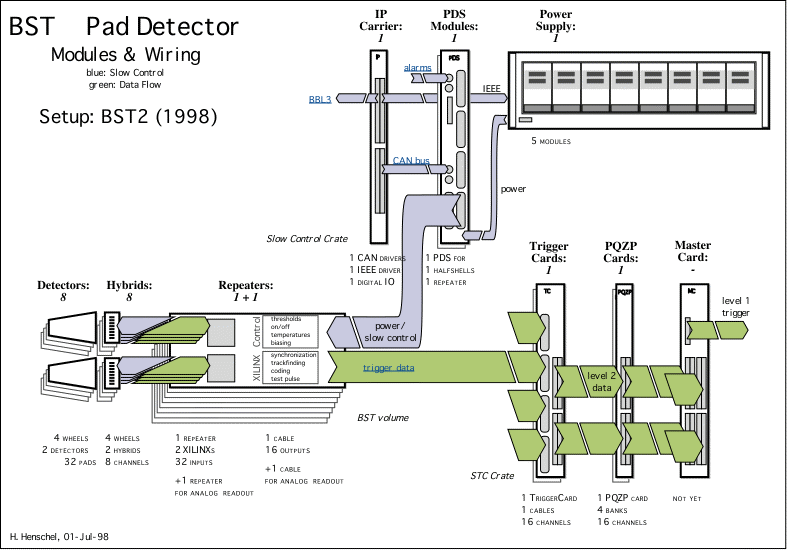
BST Pad Detector • Components Primer
(The Online Glossary contains a clickable overview!)
Overview:

Physical components:
Orange Numbers
refer to the 1998 setup.
The much larger 1996/1997 system was partly removed.
- The Pad Hybrid with pad detector and
amplifier/discriminator chips on it and integrated flexible cable
extension to the repeater (8 signals, 8 thresholds,
8 supply and operation lines). A total of 64 hybrids are
required ( 8 installed, 2 of them being
modified for readout of up to 8 analog signals in 1998
only).
Performance in H1 and several testruns showed that the
preamplifier suffers from large coherent noise of the detectors thus it
will be revised throughout this year including a common mode supression
circuit.
- The Pad Repeater processing the data input of two
adjacent sectors (8 detectors, thus 64 signals total) in two XILINX
3192A chips. It implements in addition:
- 64 input receivers, 16 long cable output drivers
- a Testpulse generator
- the XILINX configuration bus (8 XILINXs daisy-chained)
- a Slow Control CAN bus featuring the following slow control functions
per repeater:
- 8 remote controlled ON/OFF switches for detector depletion
- 8 remote controlled individually adjustable thresholds
- 8 bias current sensors, remotely read out
- 3 temperature sensors
- about 10 supply and auxiliary voltage stabilizers
- a water cooling and nitrogen flow system
A total of 8 repeaters are required ( 1
installed, another one for remote bias control and analog readout in 1998
only).
- The Power/Download Station (PDS) providing the Slow
Control-to-Repeater interface for
- the power distribution (separate IEEE controlled modular power supply)
- the XILINX configuration and check
- a configuration identifier (to be stored with the trigger data)
- the CAN bus transmission (separate VME driven CAN controller)
- Watch Dog and Alarm Generators for BBL3
A total of two PDS are required ( 1 installed).
- The Trigger Card (TC) providing the interface
between Repeater and H1 Trigger Signals (Clock, FER, L3Keep...),
implementing several phase shifters and auxiliary control signals.
A total of two TC are required ( 1 installed).
- The Master Card (MC) providing the combinational
logic for combining the 8 different sector words to a single L1 trigger
word.
A total of one MC is required ( none installed,
for test purposes a simple bypass is set up).
Operation Software:
There is a Slow Control Application programmed in LabView
running on the H1:BST Mac in the control room. Besides controlling the BST
strip detectors it handles the slow control tasks for the pads (powering,
XILINX, thresholds...) and the slow control information relevant for both
parts: temperatures, radiation and/or cooling alarms, watchdogs, BBL3
status signals...
A few lines of code are implemented in the STC taxi
readout to write BST trigger data to the H1 banks:
- SITR contains the TC status and XILINX configuration identifier
- TSCD contains the repeater output for the last 24 bunch crossings at a
triggered event.
The Frontend Data Reduction Algorithms implemented in the
XILINXs are being designed offline using a schematic editor and a
commercial development system. They are coded to bit-serial data stream
files to which a unique identifier is added upon configuring the system in
H1.
© by Hans Henschel, 23-feb-98, last revised:
06-oct-98

