 half
half
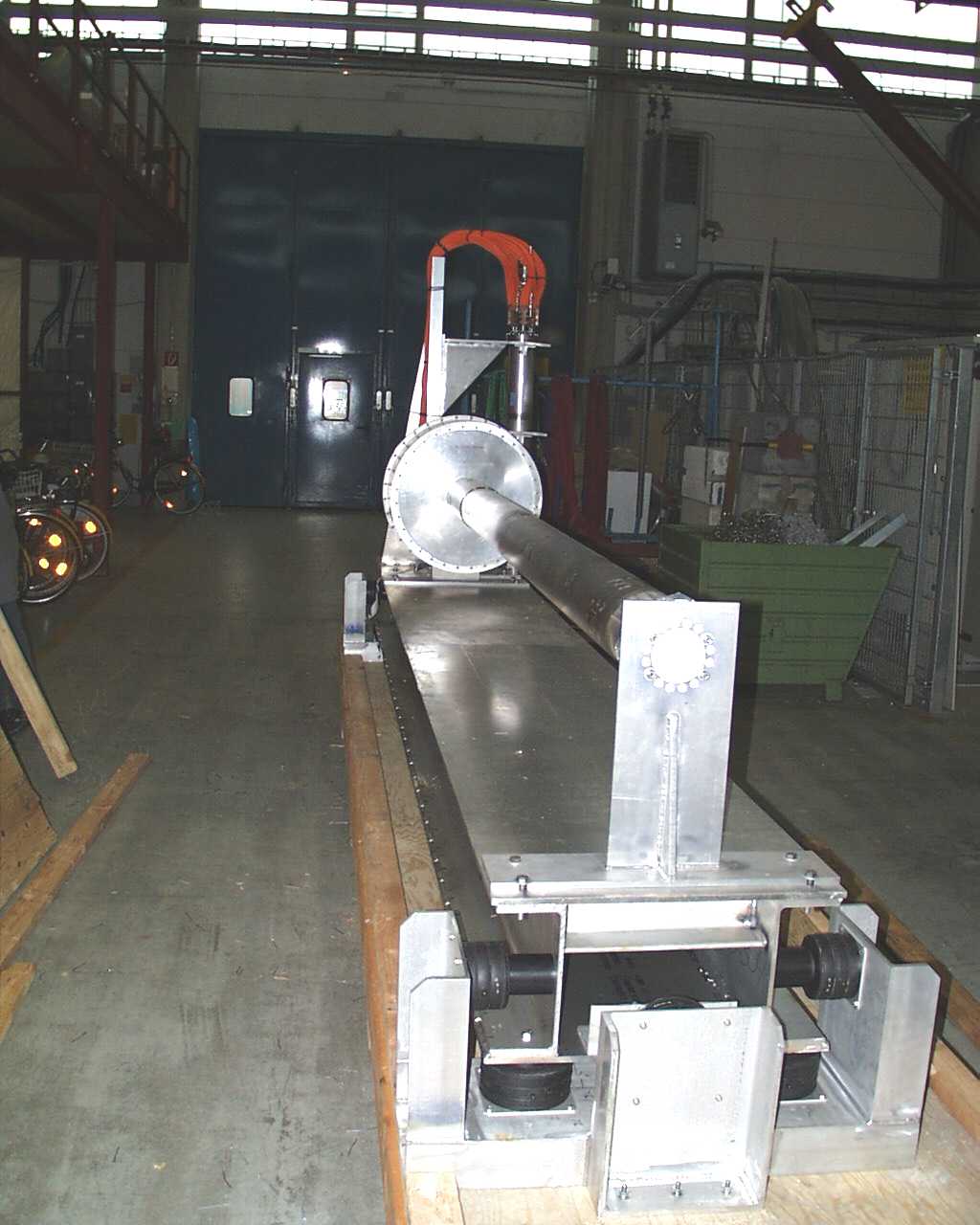
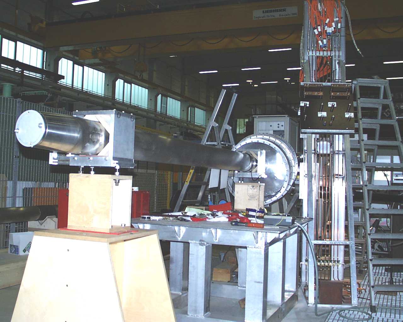
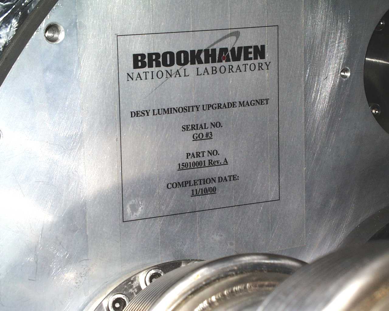
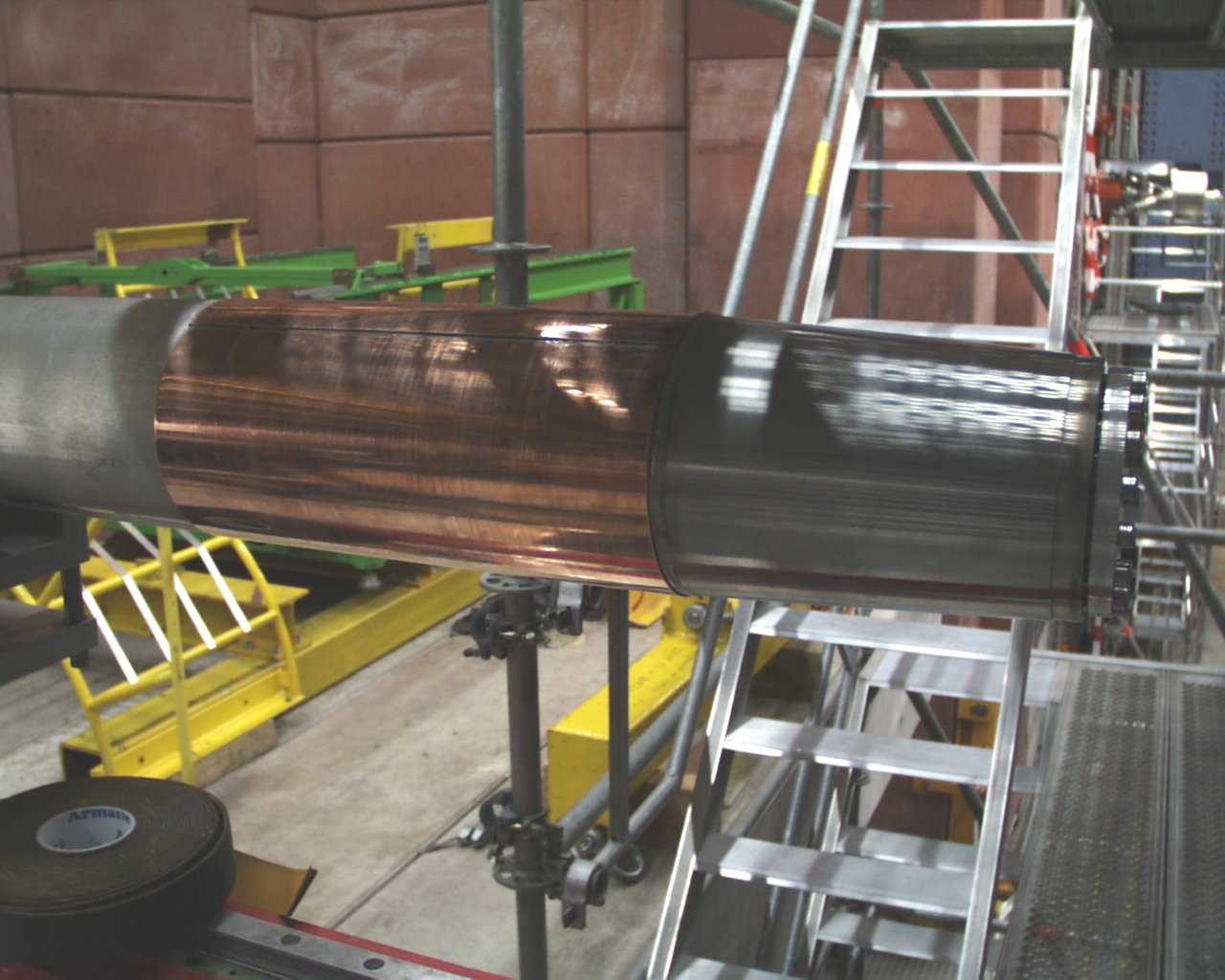
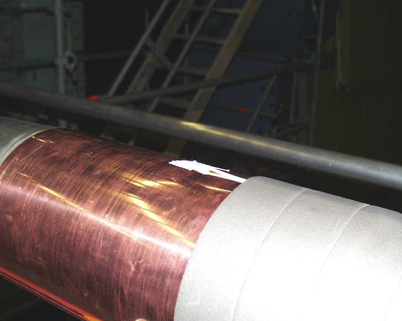
GO #3 arrives at DESY for H1
 half
half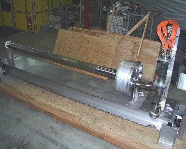
 half
half
 half
half
 half
half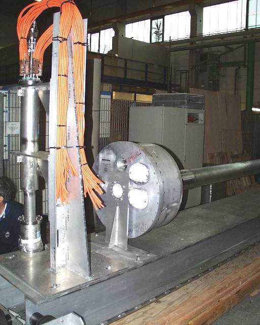
 half
half
 half
half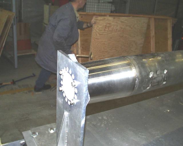
 half
half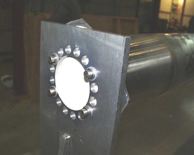
 half
half
 half
half
 half
half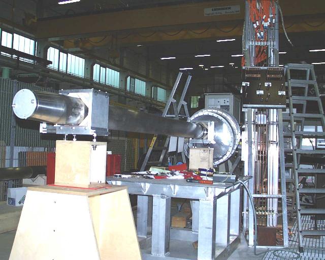
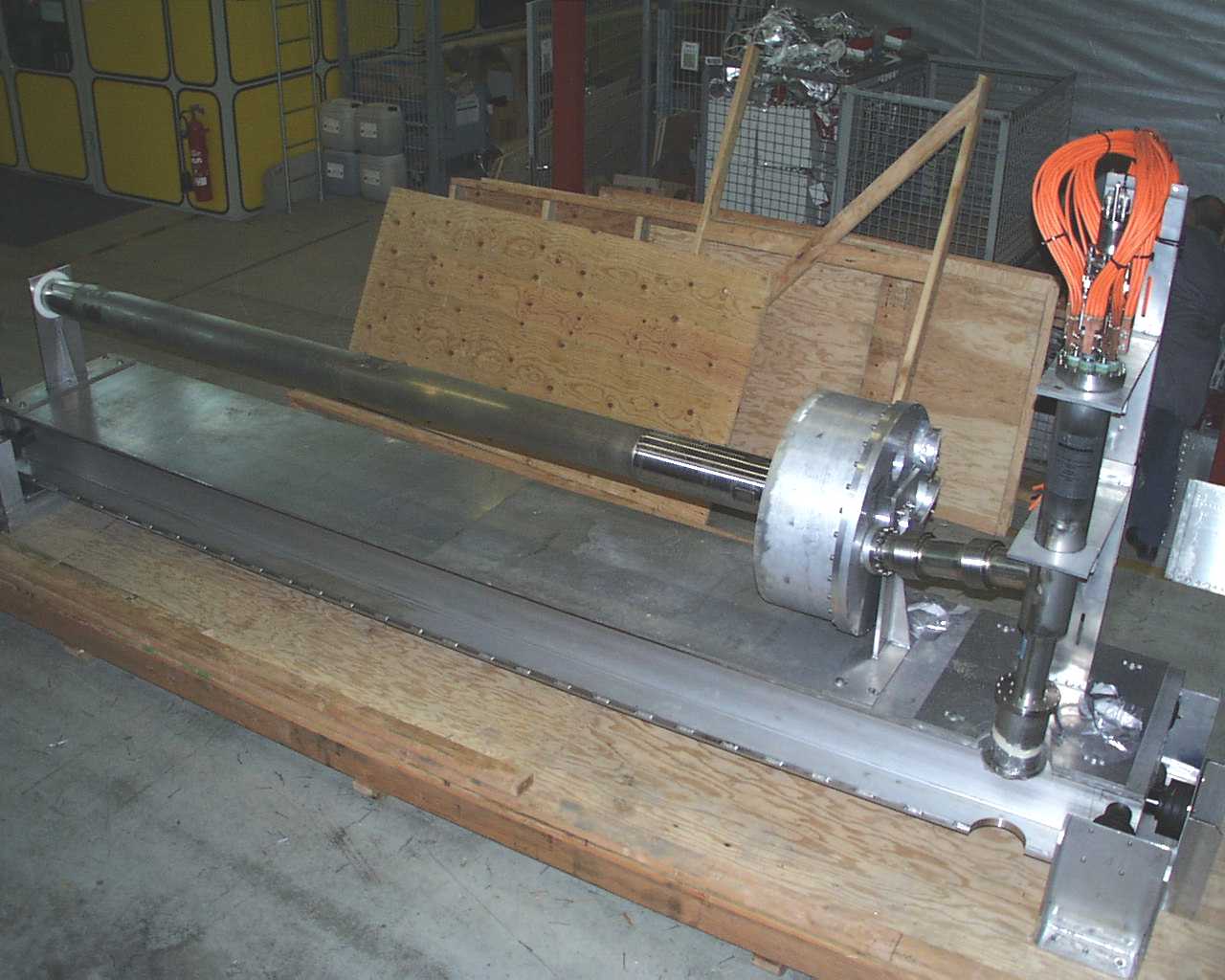
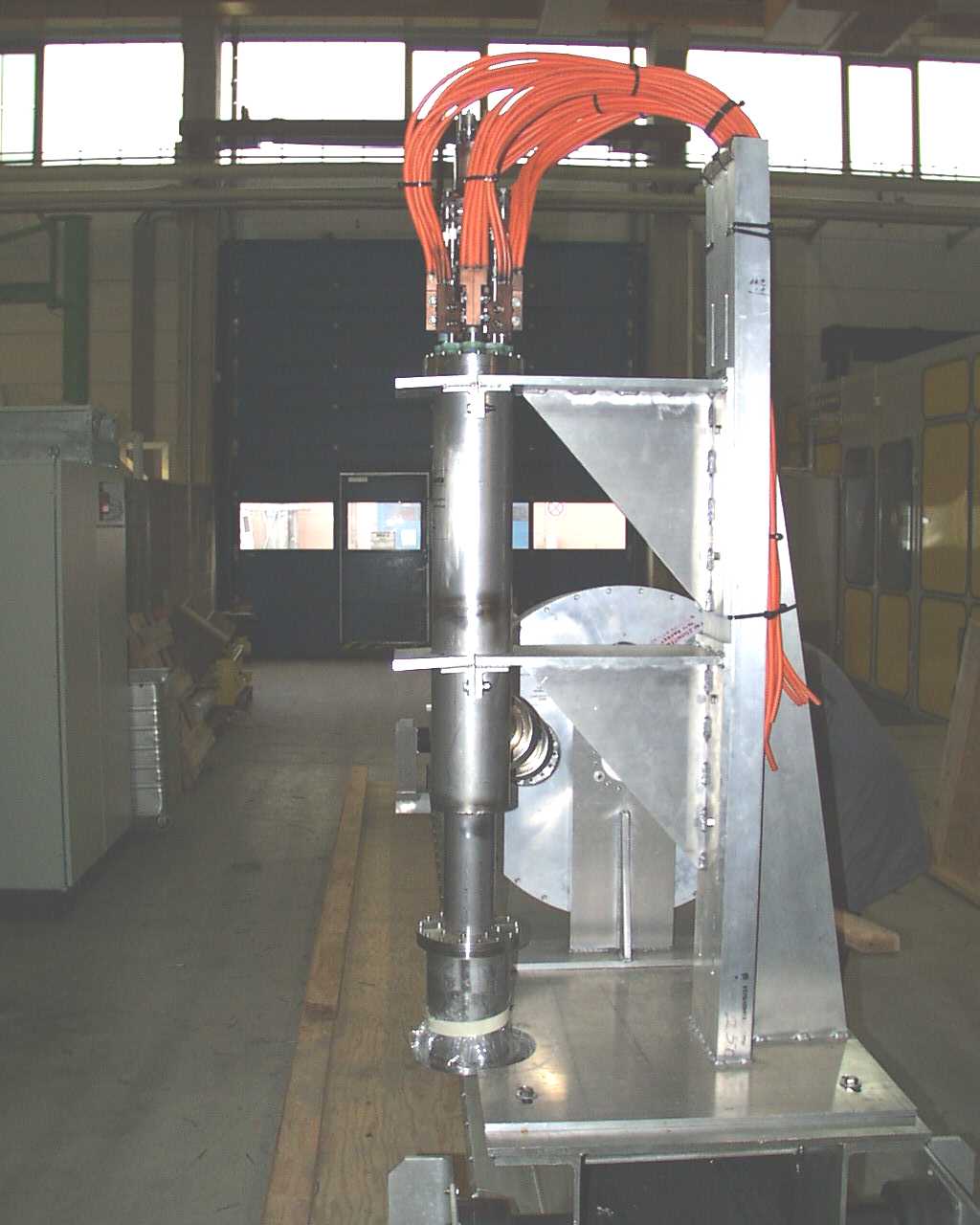
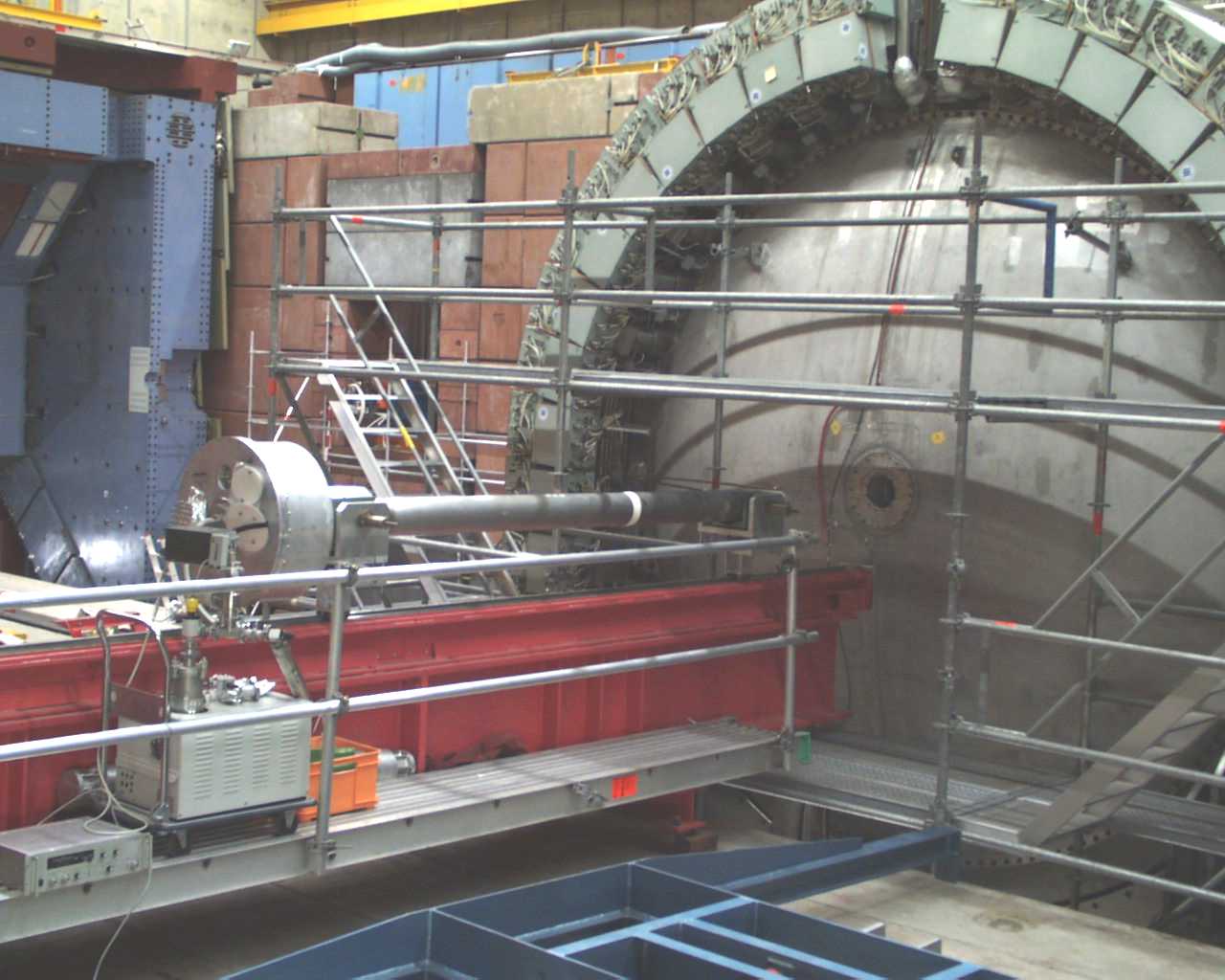
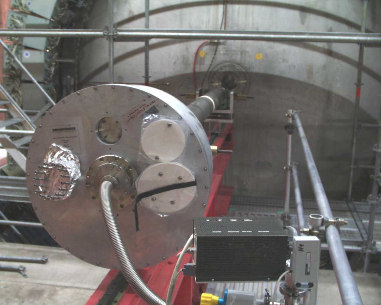
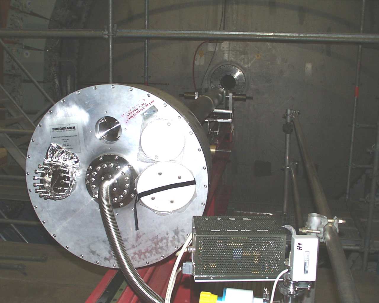
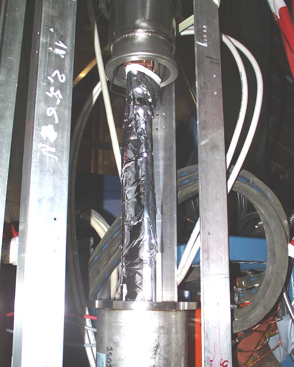
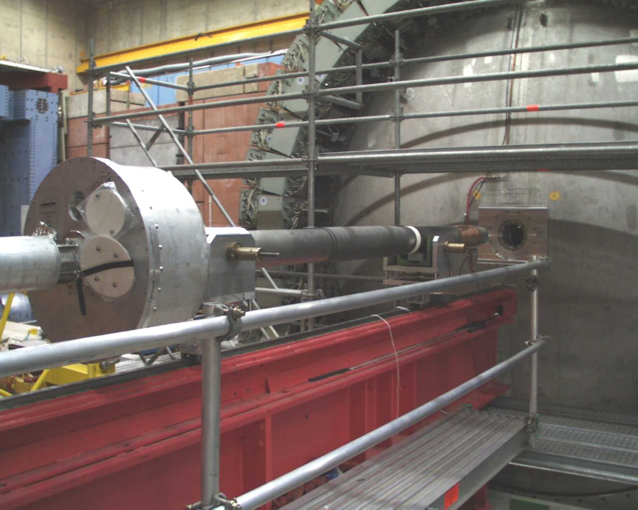
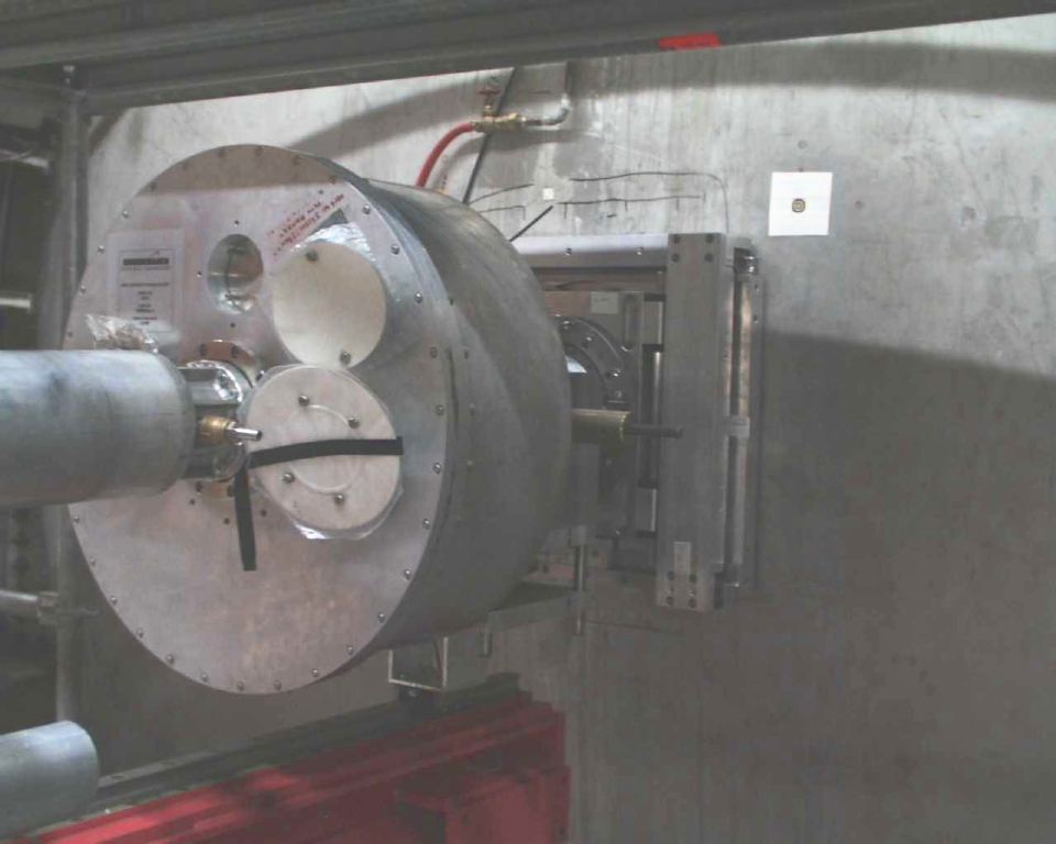
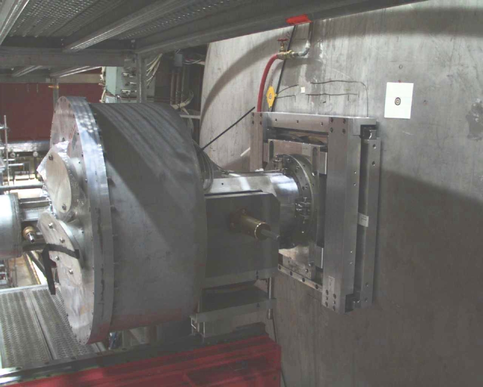
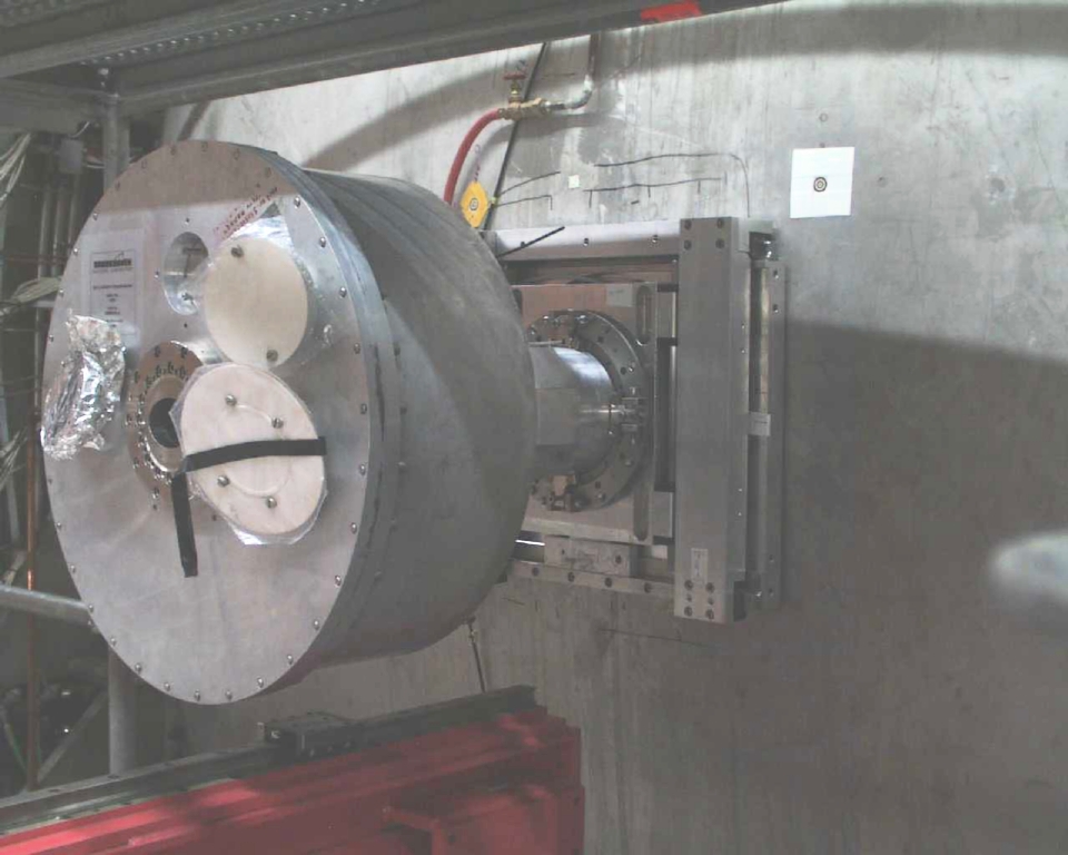
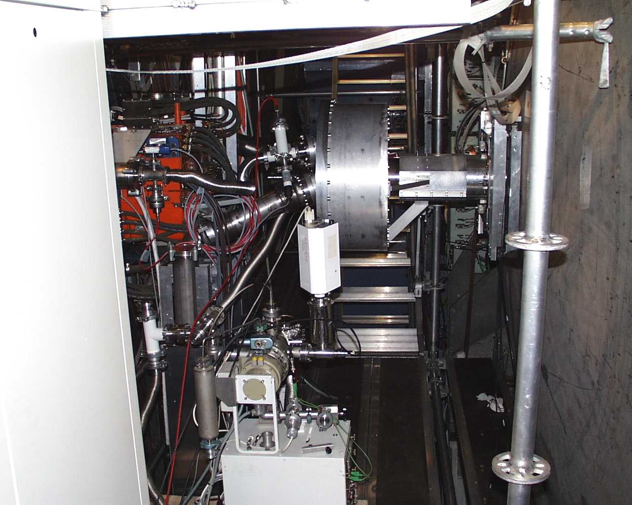
GO #3 on magnet test stand, hall 55
 half
half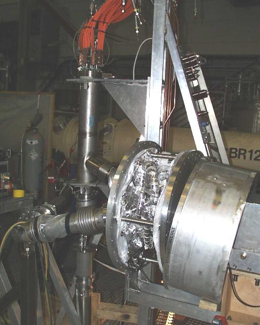
 half
half
 half
half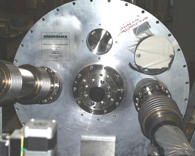
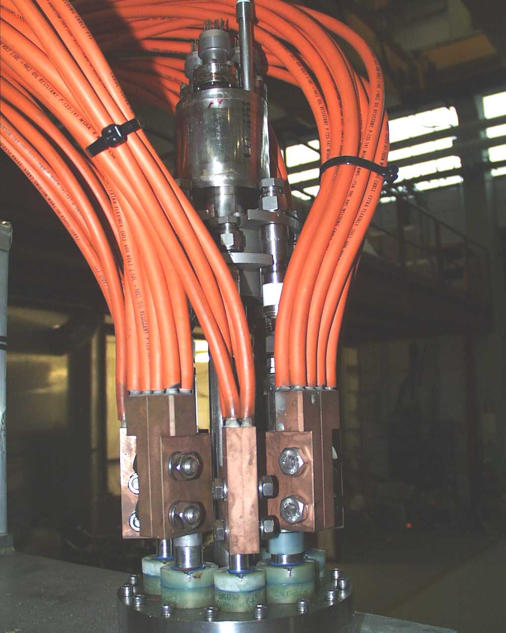
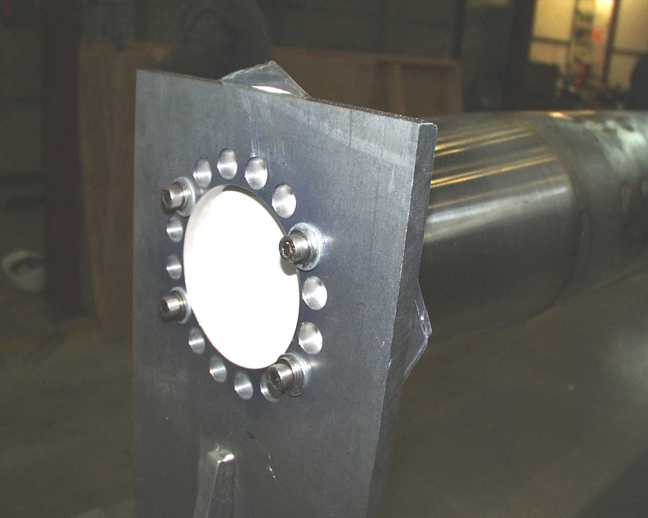
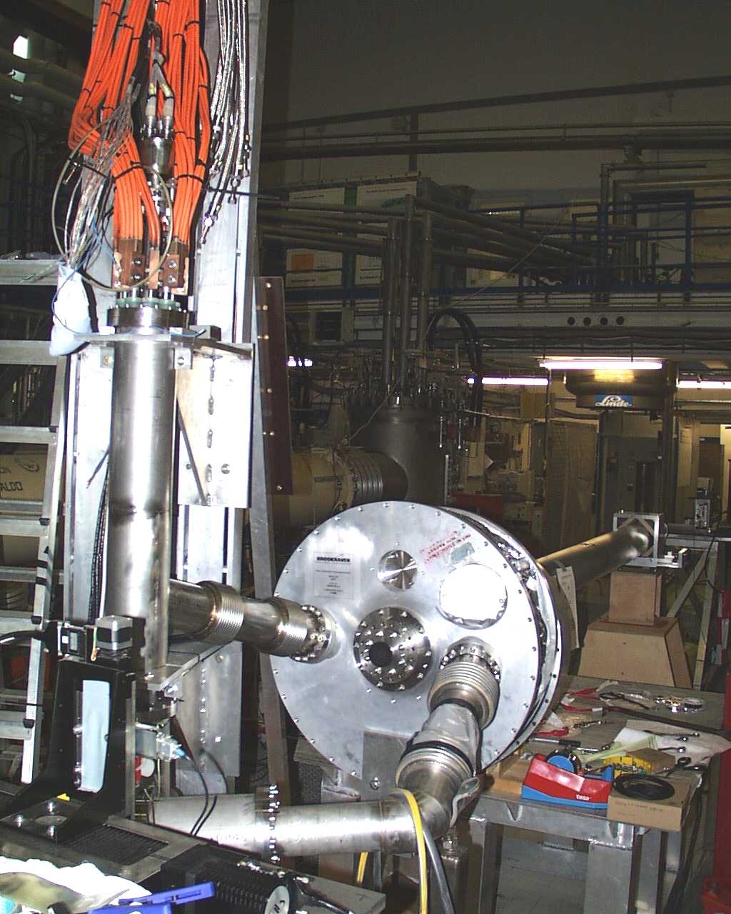
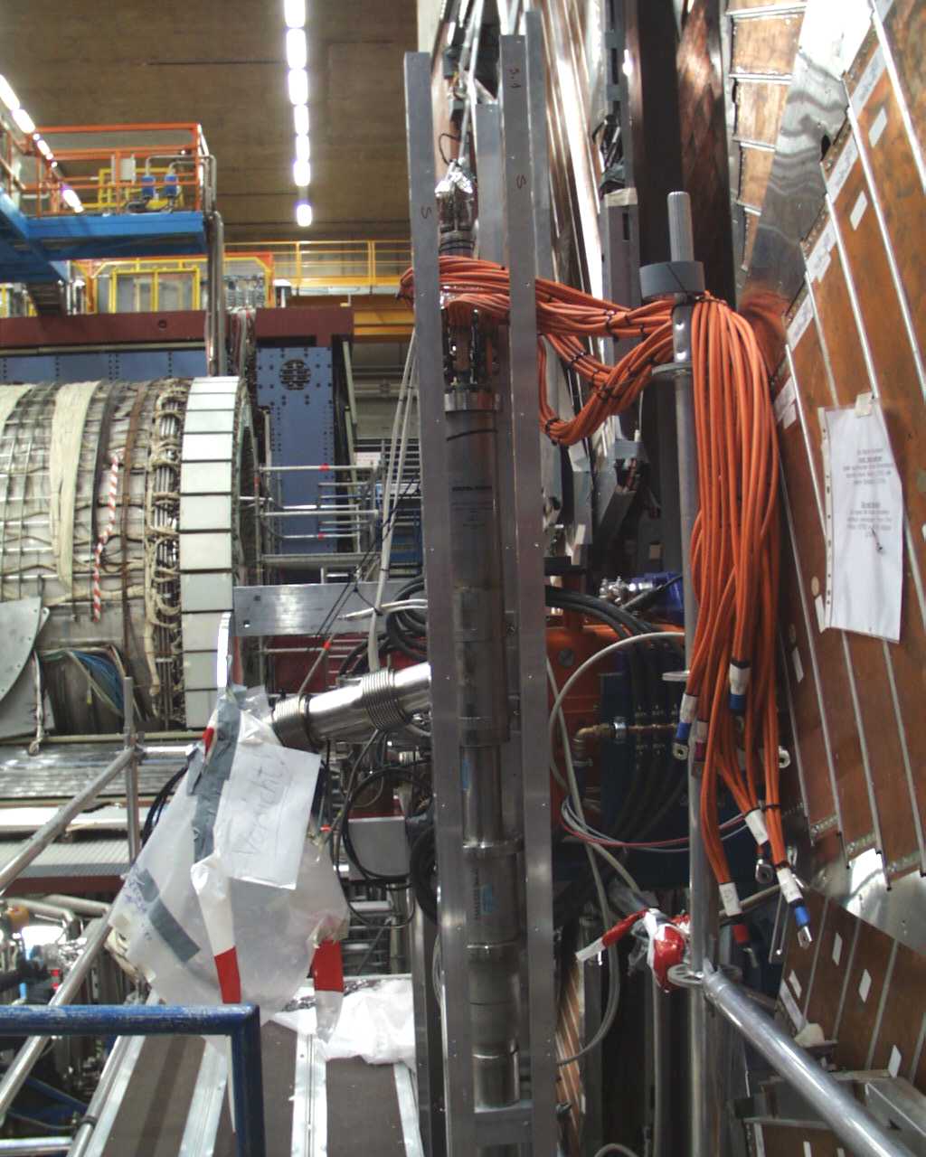
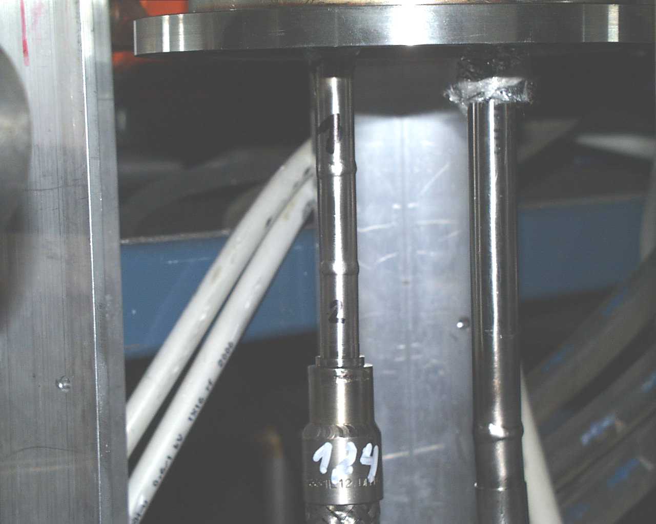
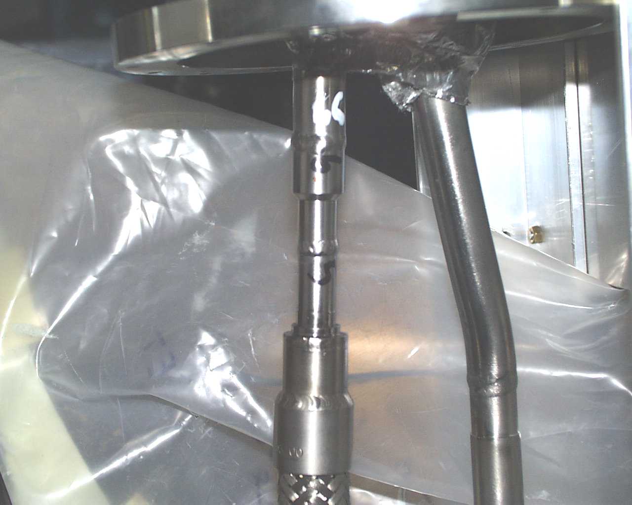
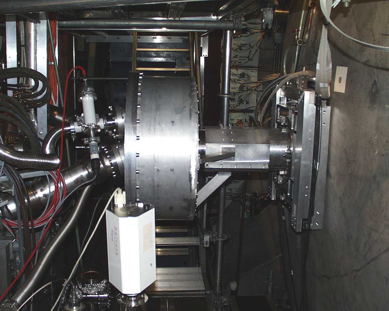
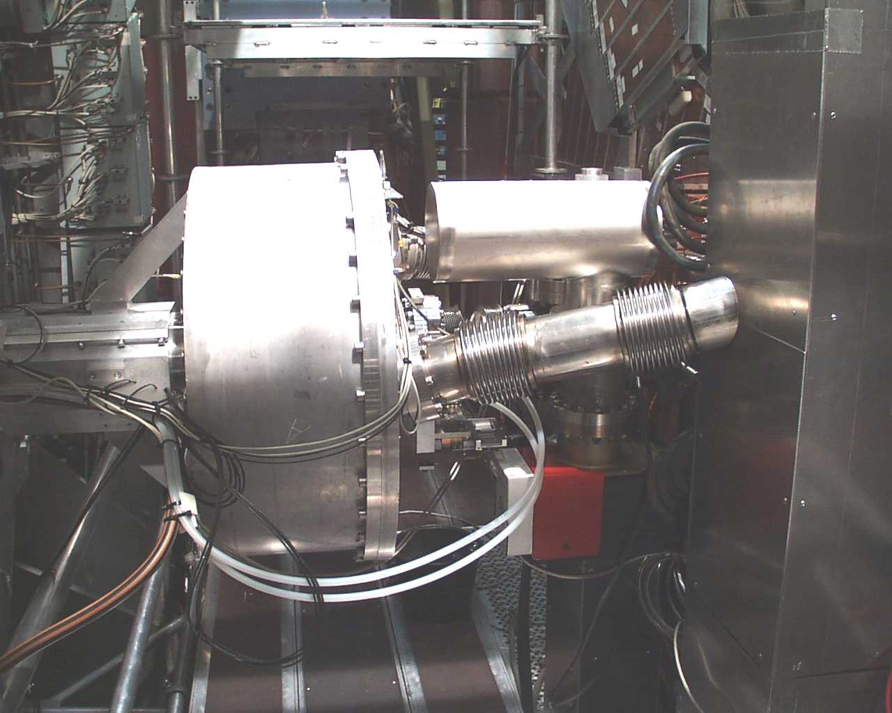
right: helium in, center: beam pipe
 half
half
 small
small
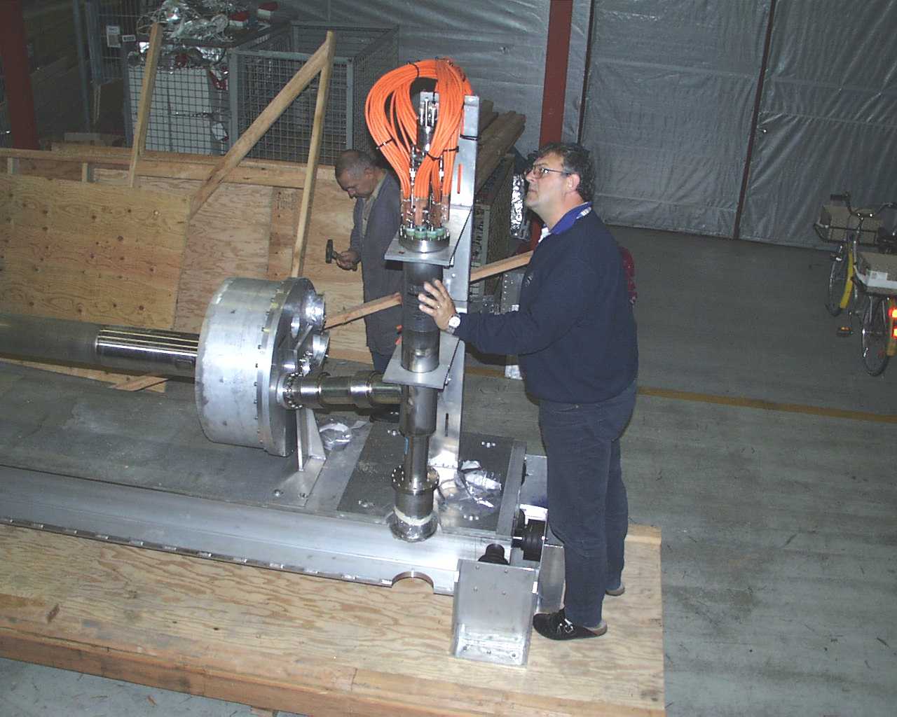
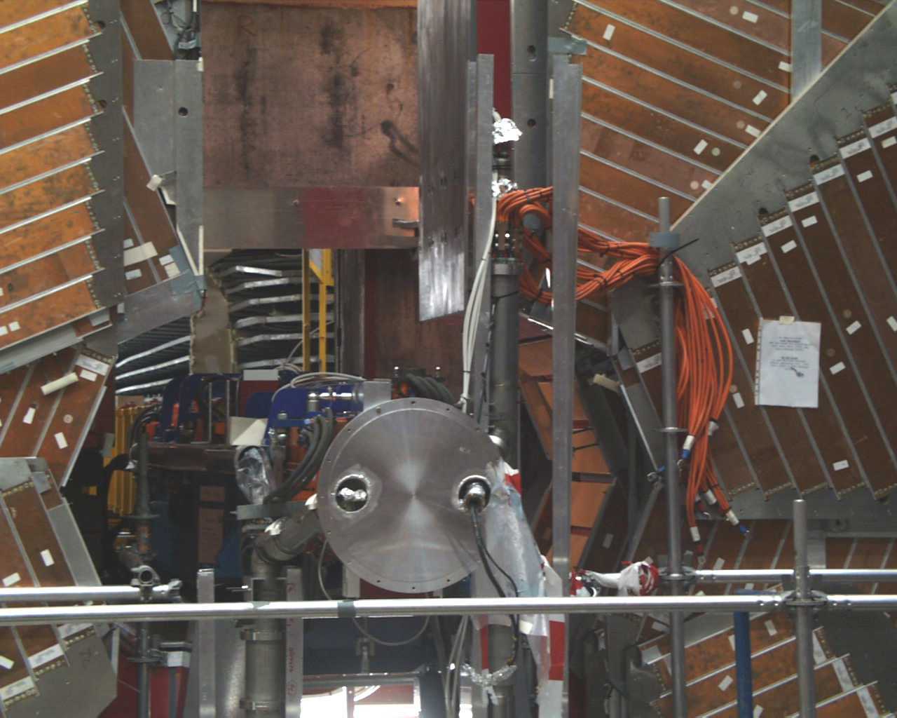
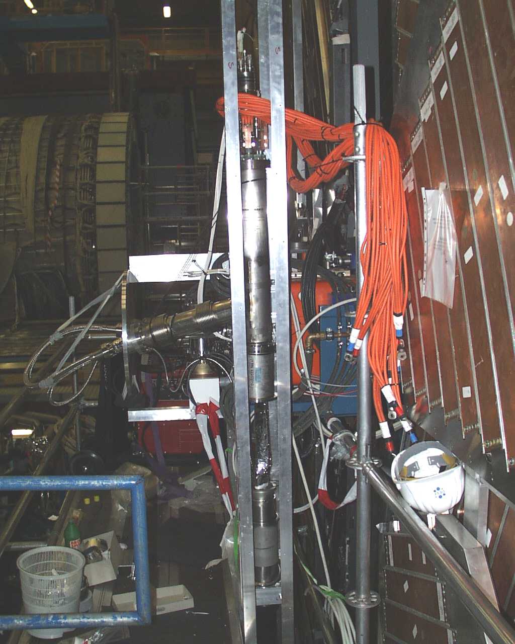
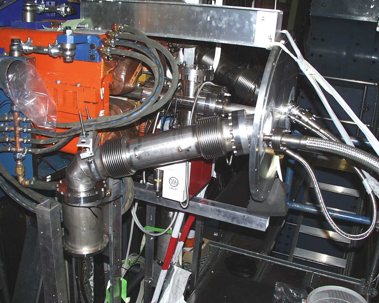
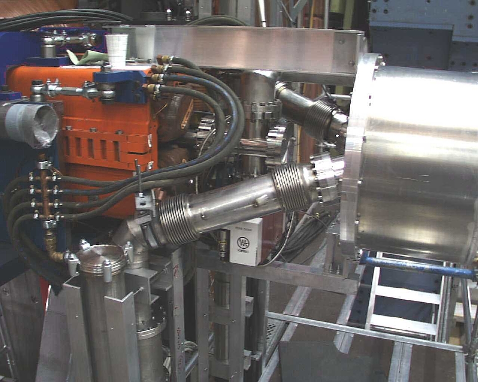
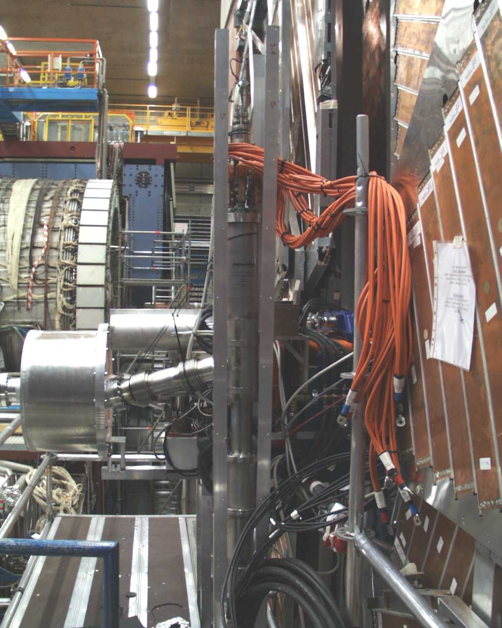
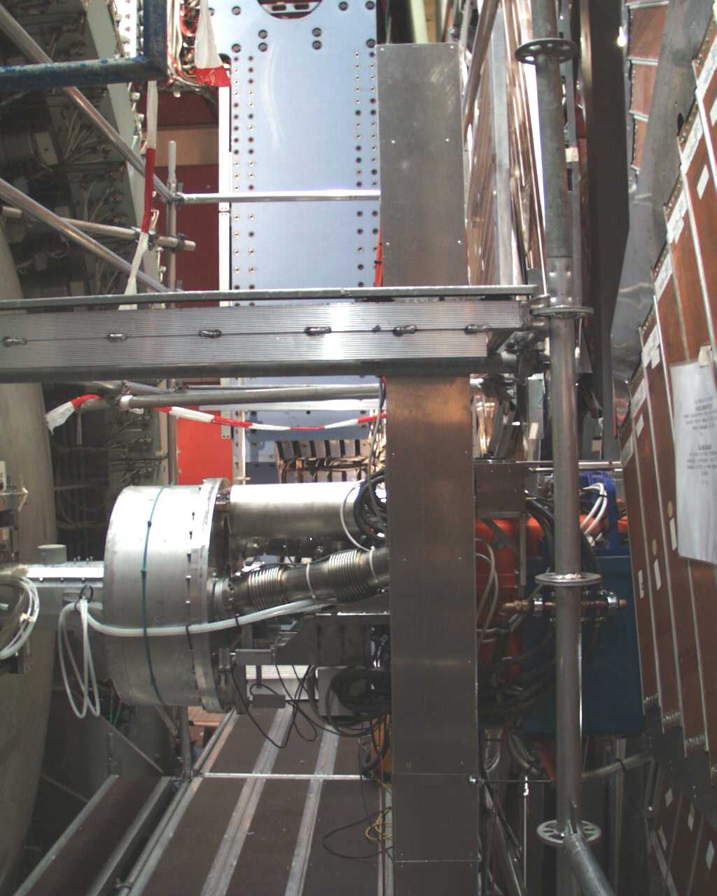
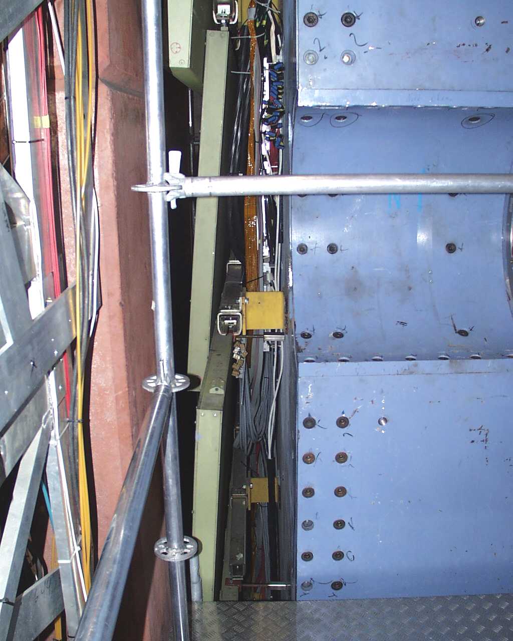
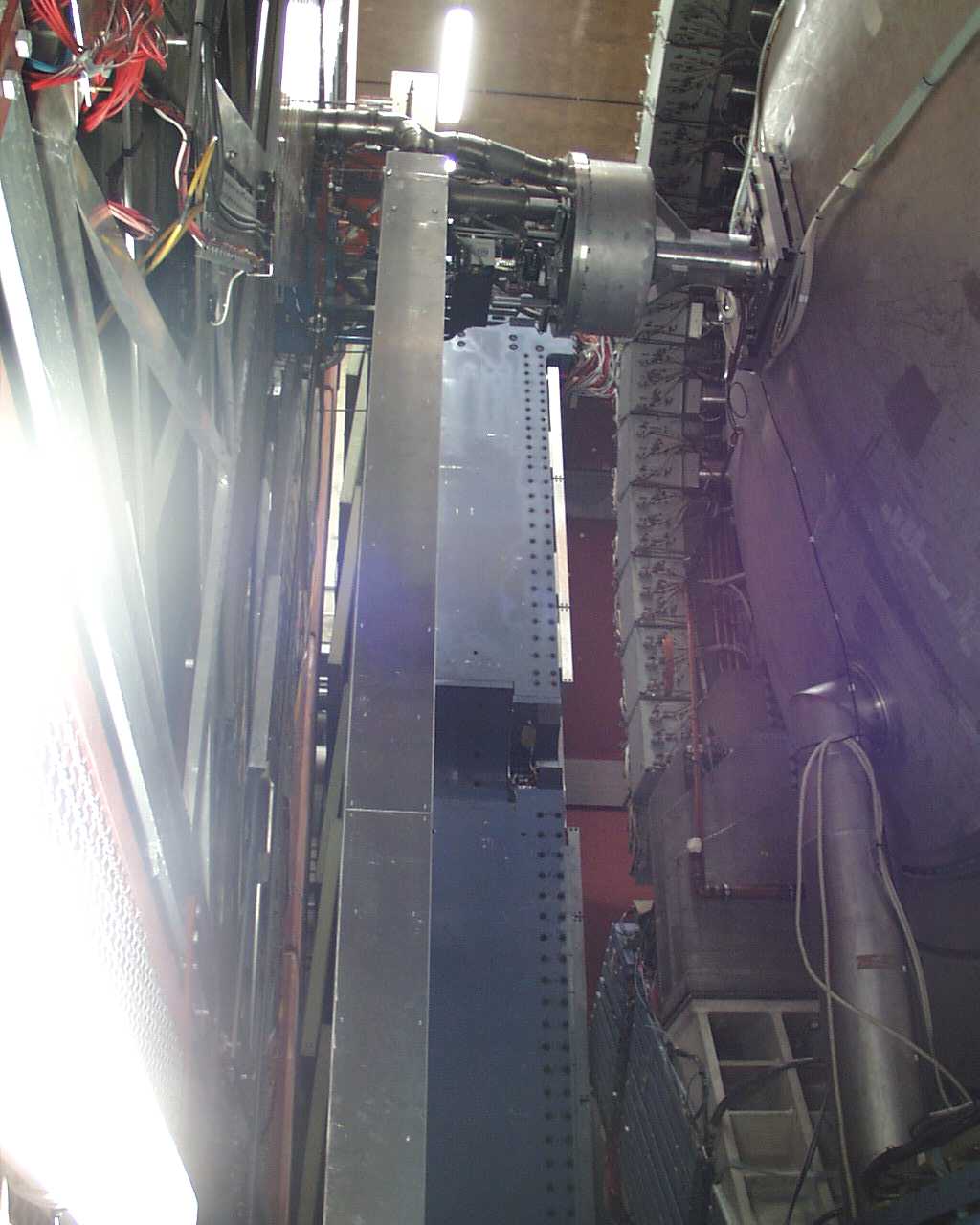
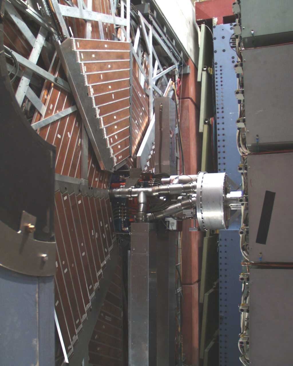
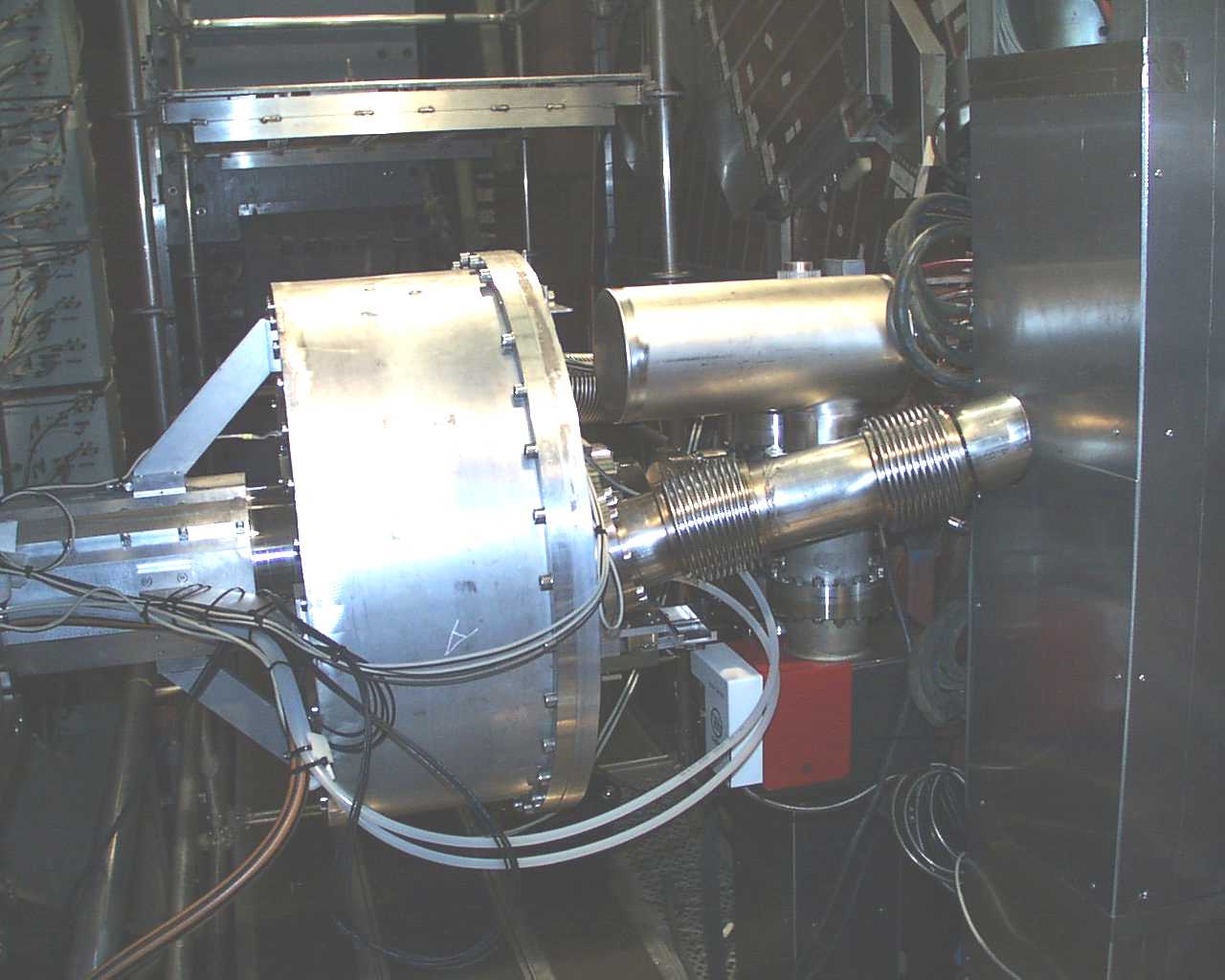
GO in Hall North
 small
small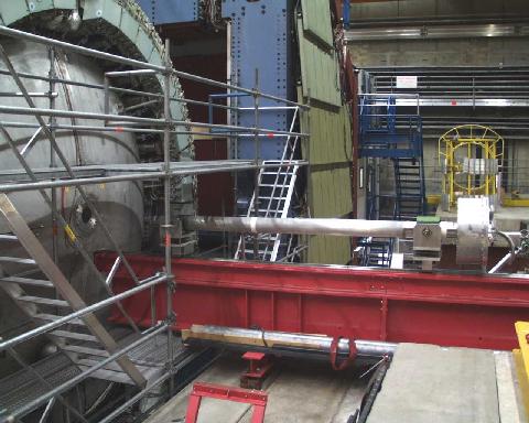
 small
small
 small
small
 small
small
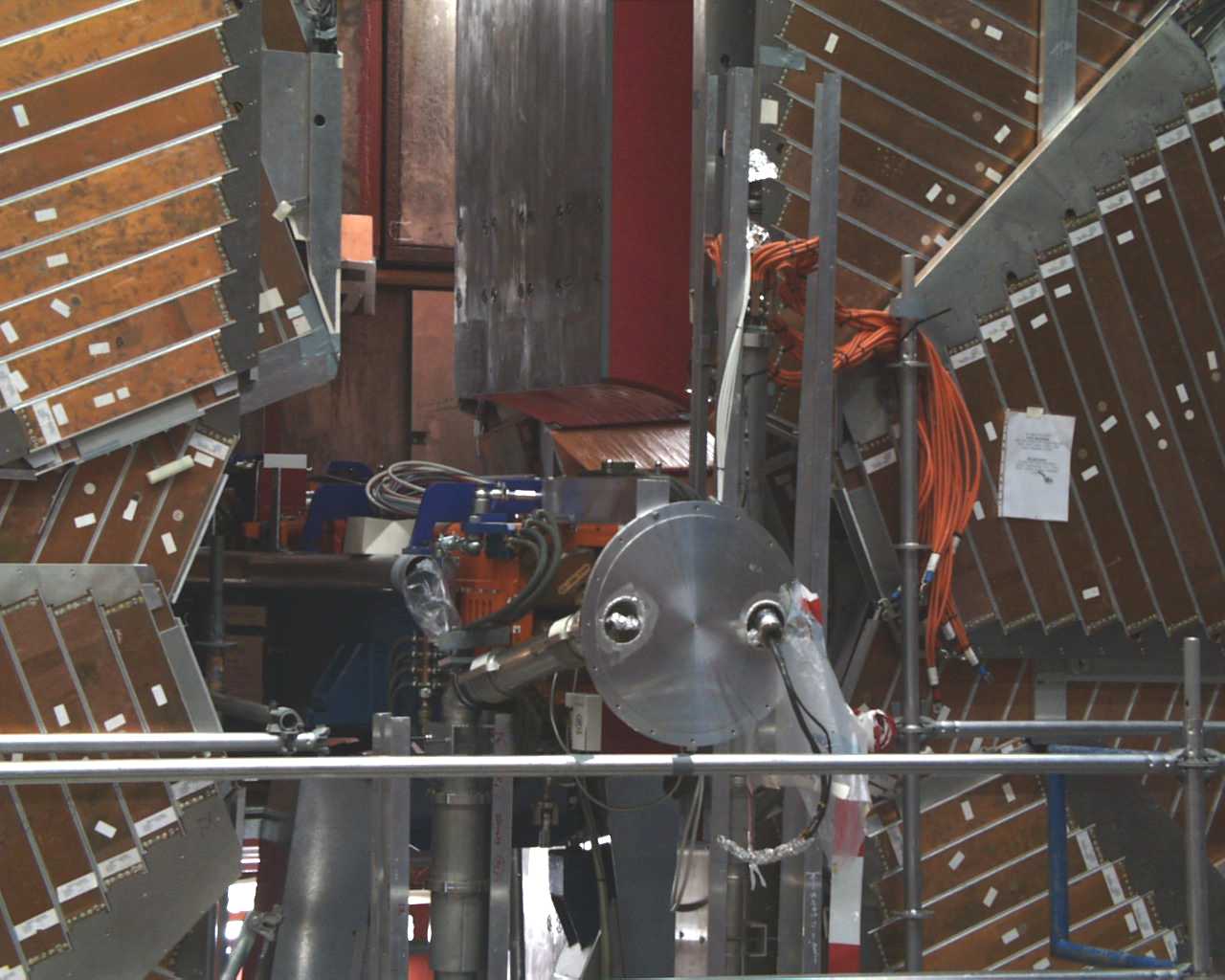
GO lead tower installed
 small
small
 small
small
 small
small
 small
small
 small
small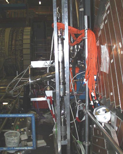
 small
small
 small
small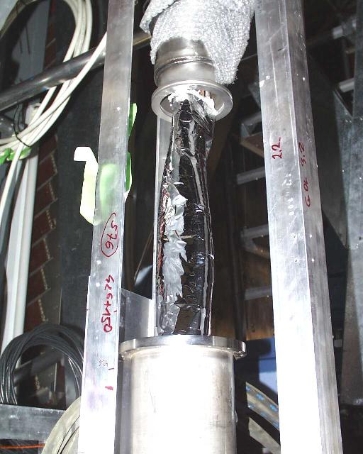
 small
small small
small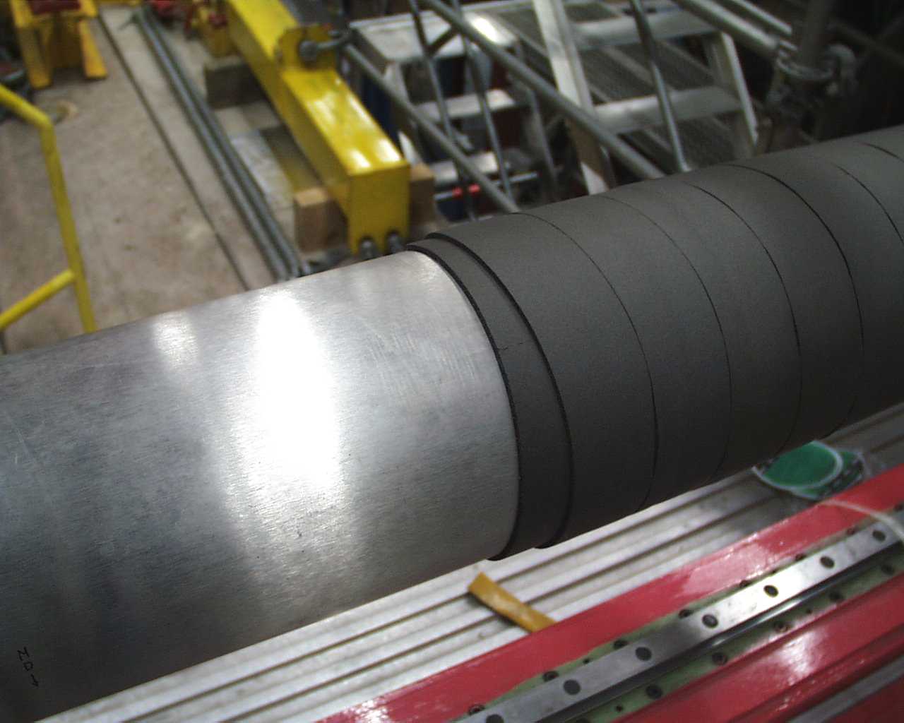 small
small
 small
small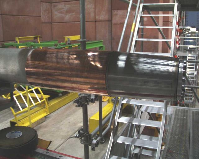
 small
small
 small
small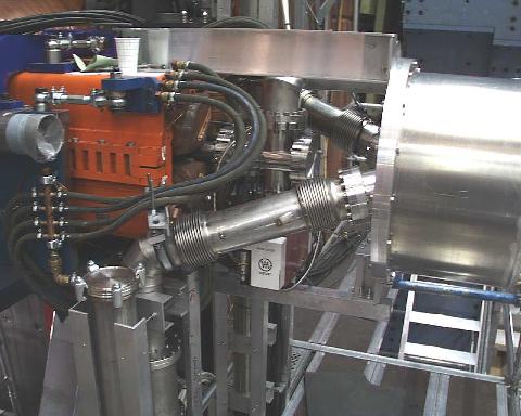
 small
small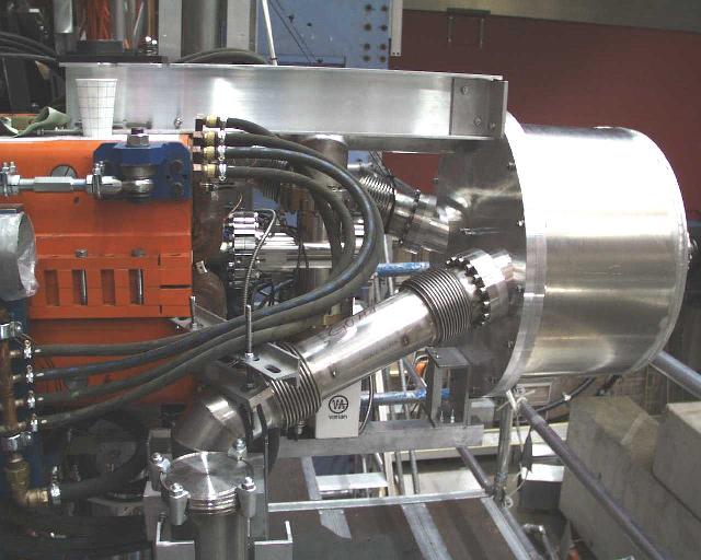
 small
small
 small
small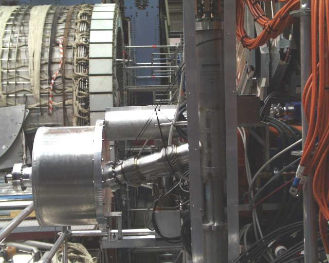
 small
small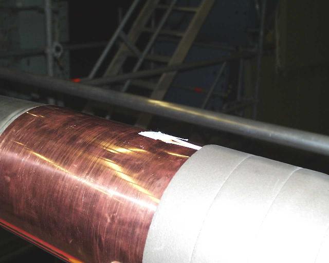
 small
small
 small
small
 small
small
 small
small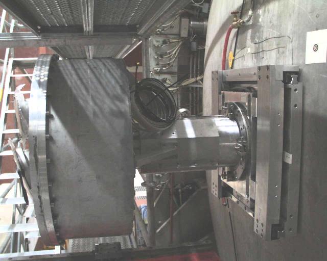
 small
small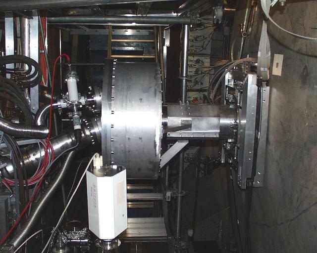
 small
small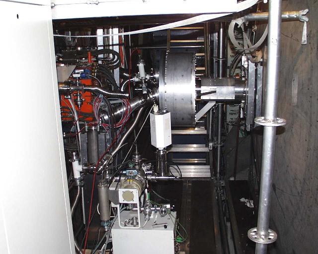
 small
small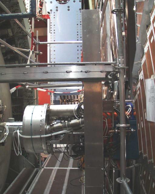
 small
small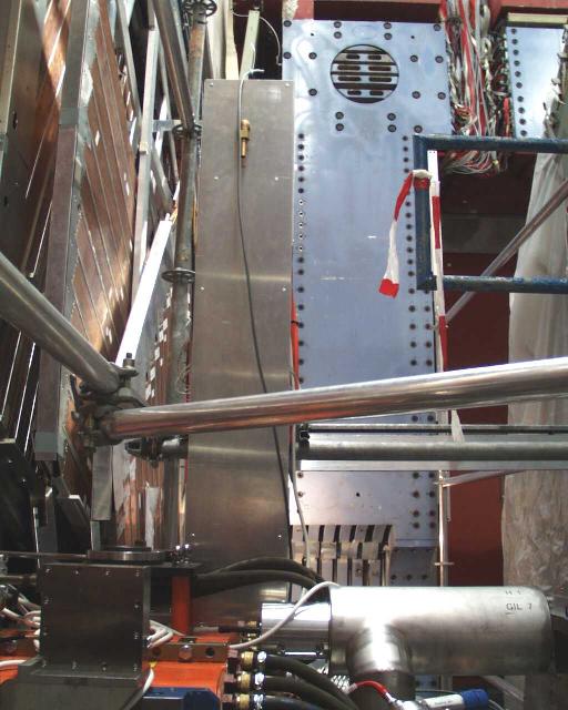
 small
small
 small
small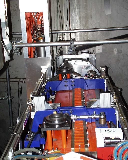
 small
small
 small
small
 small
small
 small
small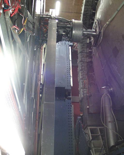
 small
small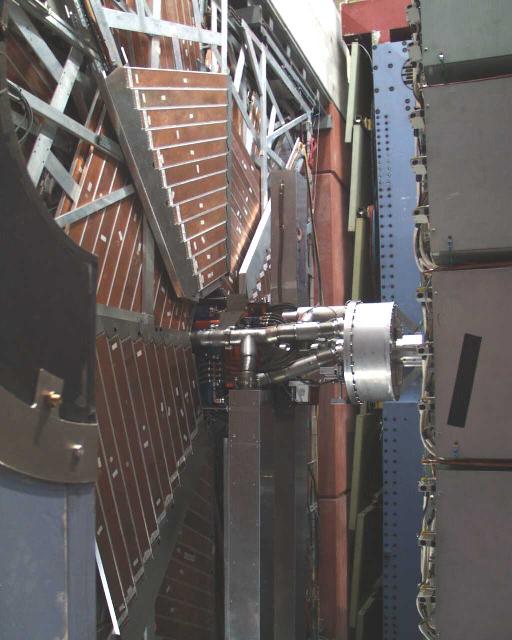
 small
small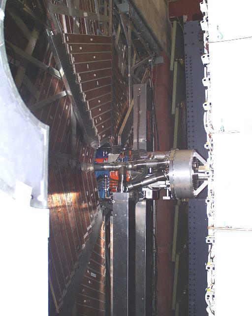
 small
small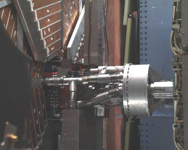
 small
small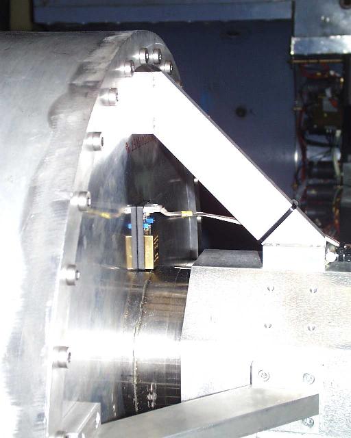
 small
small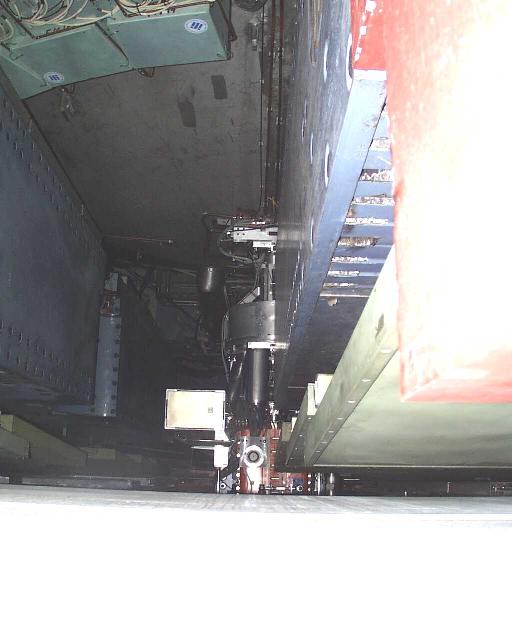
 small
small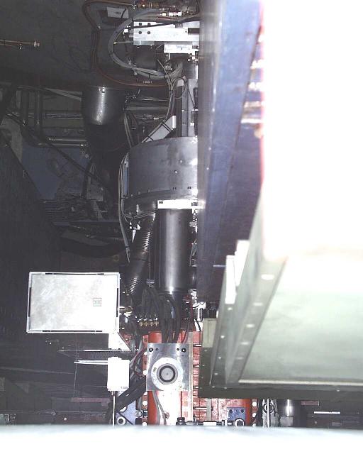
 half
half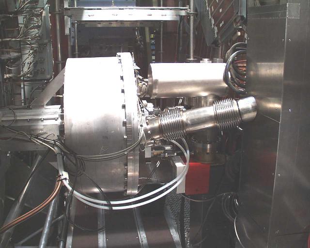
 half
half