|
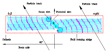
The central inner z-chamber CIZ (as well as the central outer Z-chamber
COZ )
is designed to measure the z-coordinate of the track position much more precise
than it is achieved by charge division of the CJC signals. The sense wires are strung concentrically and perpendicular around the beam axis. The cross section of CIZ forms a 16-edge- and that from the COZ a 24-edge-polygon. The CIZ (COZ) is subdivided into 15 (24) rings in z with each ring having four wires. The active regions covered by CIZ (COZ) are given together with those of the CST and CJC in Table 1 |
|
|||||||||||||||||||||||||||||||||||||||||||||||||

|
| corresponds to the ring numbers 9-14 of the positive z-region. The tilt changes to the opposite direction for the negative z-region (rings 0-8). Cell coordinates (z',u) are defined with the z'-axis parallel to the beam axis and the u-axis normal to the wire and the beam axis and the origin at the center of the drift cell. Geometrical parameters of the CIZ and the COZ relevant for the calibration are summarized in Table 2 |
|
|
More informations concerning construction, performance, calibration etc. may be found elsewhere: Thesis of P. Robmann (office Zürich), M. zur Nedden , S. Hengstmann or Journal: P. Robmann et al., Nucl. Instr. and Meth 277, 368 (1989), S. Egli et al., Nucl. Instr. and Meth 283, 487 (1989). |
HOME