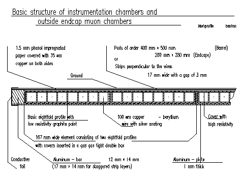
Schematic view of a single layer of the Tail Catcher
The iron yoke of the main solenoid magnet is interleaved with limited streamer tubes (LST). The purpose of the LST's is twofold: the detection of muons and the determination of the hadronic leaking energy out of the Liquid Argon Calorimeter (LAC).

Schematic view of a single layer of the Tail Catcher
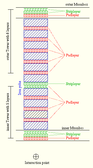
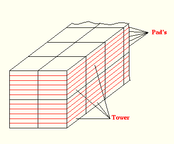
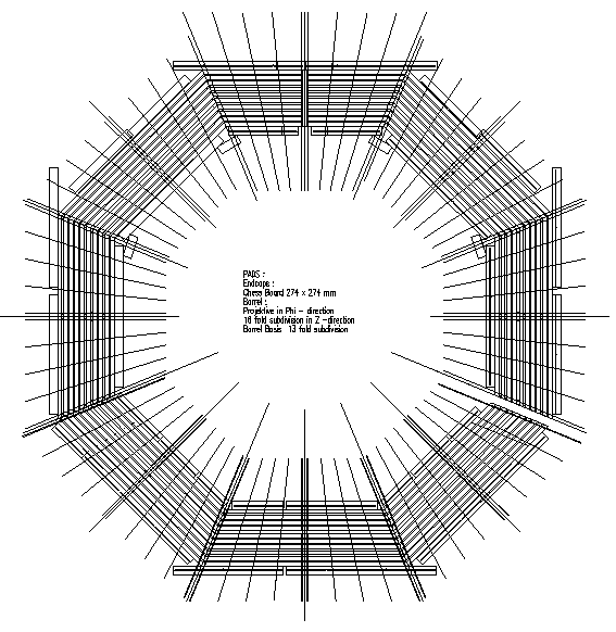
The readout of the LST's is split into two parts, a) wire readout, b) pad readout. Each wire of a LST is connected to a single input of the readout chain. Wire signals passing an external threshold are converted into digital signals. The digital information is stored in an output bank named IRWE which contains the geometric numbers of these wires. The disadvantage this method is the lake of information whether one or more streamer occurs along the wire and where it happened (along the wire direction). This problem is solved by the analog readout of the LST's with electrodes (Pads). Along the wire direction up to nine pads are used for the analog readout. As the hadronic shower is spread over the area of several LSTs and in order to reduce the number of channels the pad size is chosen in the following way: 27 * 27 cm2 for the endcaps and up to 40 * 50 cm2 for the barrel. To measure also the shower development in some respect the signal of pads perpendicular to the direction of the layers are summed up into two groups of 5 or 6. This is done by amplifiers named tower builders (TB).


In order to get also the second coordinate of a muon track some LST-layers are equipped with strips instead of pads. The first three layers (two layers with strips and one layer with pads) and the last three layers layers (also two layers with strips and one layer with pads) are housing inside the so called muon-boxes as it is shown by the figure.

In the barrel the pad size increases as the radius increase as it is
shown by the figure. The pad size of the endcaps is constant.
Between Spacal and backward endcap of the Tail Catcher there is no
inner muon-box and the pad-layers of the outer muon-box of the forward endcap
were excluded from the summation in the tower builders in 1994.
The geometry of the Tail Catcher is summarized by the following table.
| Region | Range (Theta) | Segmentation | # of Channels | # of Layers inner Tower | # of Layers outer Tower |
|---|---|---|---|---|---|
| Forward Endcap | 4° - 33° | x and y | 552 | 5 | 5 |
| Barrel | 33° - 137° | phi and z | 2784 | 5 | 6 |
| Backward Endcap | 137° - 172° | x and y | 552 | 4 | 6 |
In total the Tail Catcher is made of 3888 channels and covers the polar angle range of 4° to 172°. The towers are combined to 64 modules as the digital part of the instrumented iron. Each endcap consists of 16 modules. The barrel is divided into the forward and backward part. Each part also consists of 16 modules. The numbering scheme is the same as the digital readout of the instrumented iron. There is only one difference due to the segmentation of the Tail Catcher in inner and outer towers. The modules are also divided in inner and outer modules.
| Year | Module number of missing Muon-boxes | |||||
|---|---|---|---|---|---|---|
| Forward Endcap | Barrel | Backward Endcap | ||||
| inner | outer | inner | outer | inner | outer | |
| 1992 | 48 - 63 | 48 - 63 | 32, 34 - 37, 39 | 16 - 24, 31 - 40, 47 | - | 0 - 15 |
| 1993 | - | - | - | 16, 23, 24, 31, 32, 39, 40, 47 | - | - |
| since 1994 | - | 48 - 63 | - | 16, 23, 24, 31, 32, 39, 40, 47 | - | - |
In addition the whole iron instrumentation of the modules 19, 20, 35 and 36 (top of the barrel) was missing in 1992.