 |
Soldering of micro-coax cables for pad readout |
 |
Signal fan-in on a 128 pin connector, 0.5 mm pitch |
 |
Fill with Araldit glue |
 |
First complete pad layer |
 |
First 4 layers in bake-out oven |
 |
Transfer wires from a wiring frame to the chamber |
 |
Test of the prototype chamber |
 |
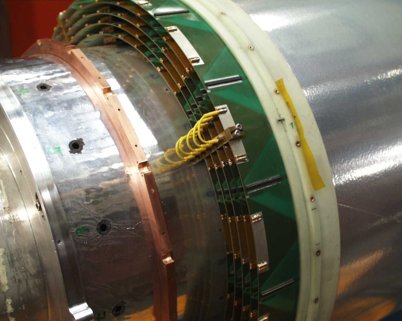
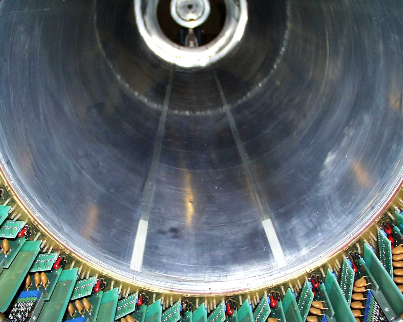
3D view of the CIP end flange with on-chamber electronics, gas, and HV connectors |
 |
Readout schematics |
 |
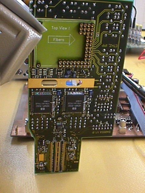
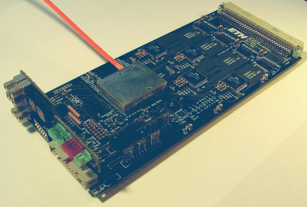
CIPIX readout board, 1999 prototype |
 |
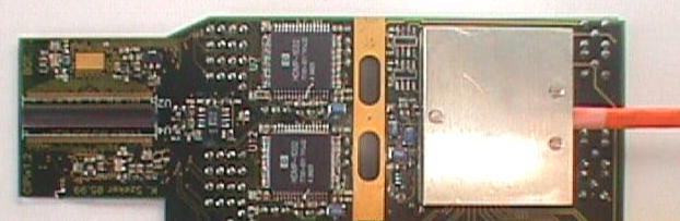
Protoype with optical hybrid and cable |
 small small |
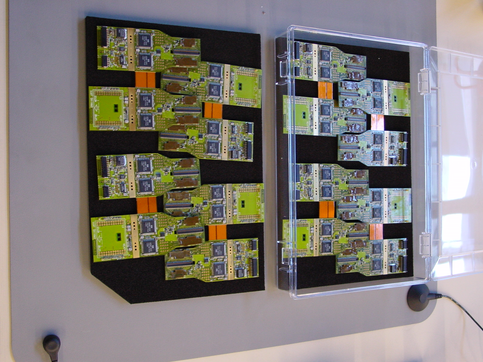
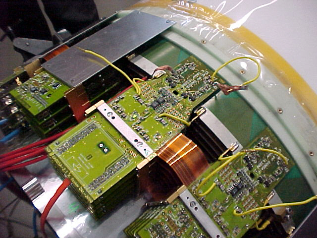
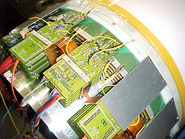
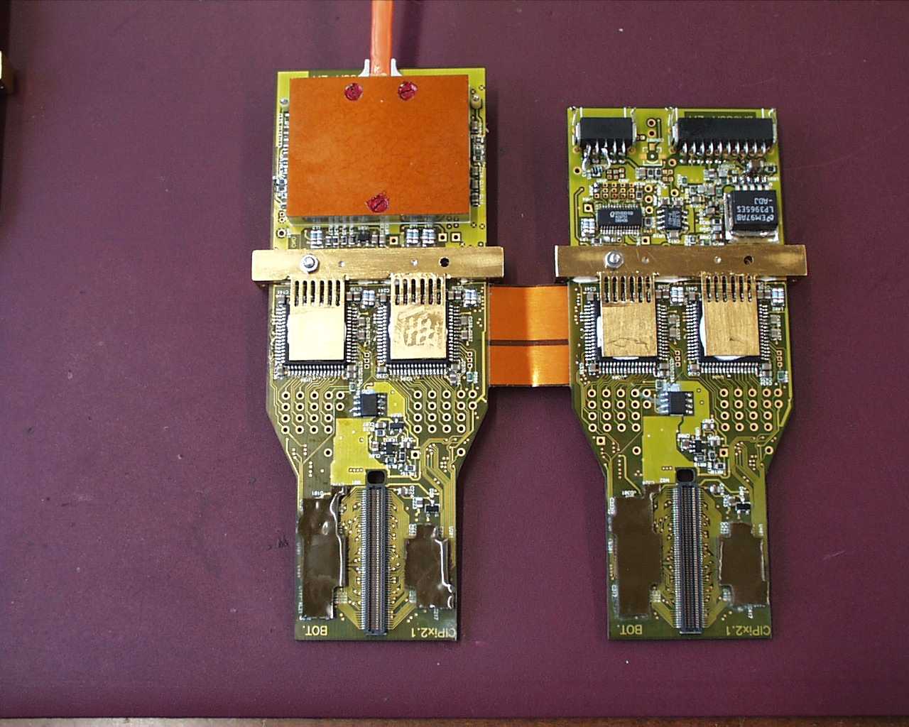
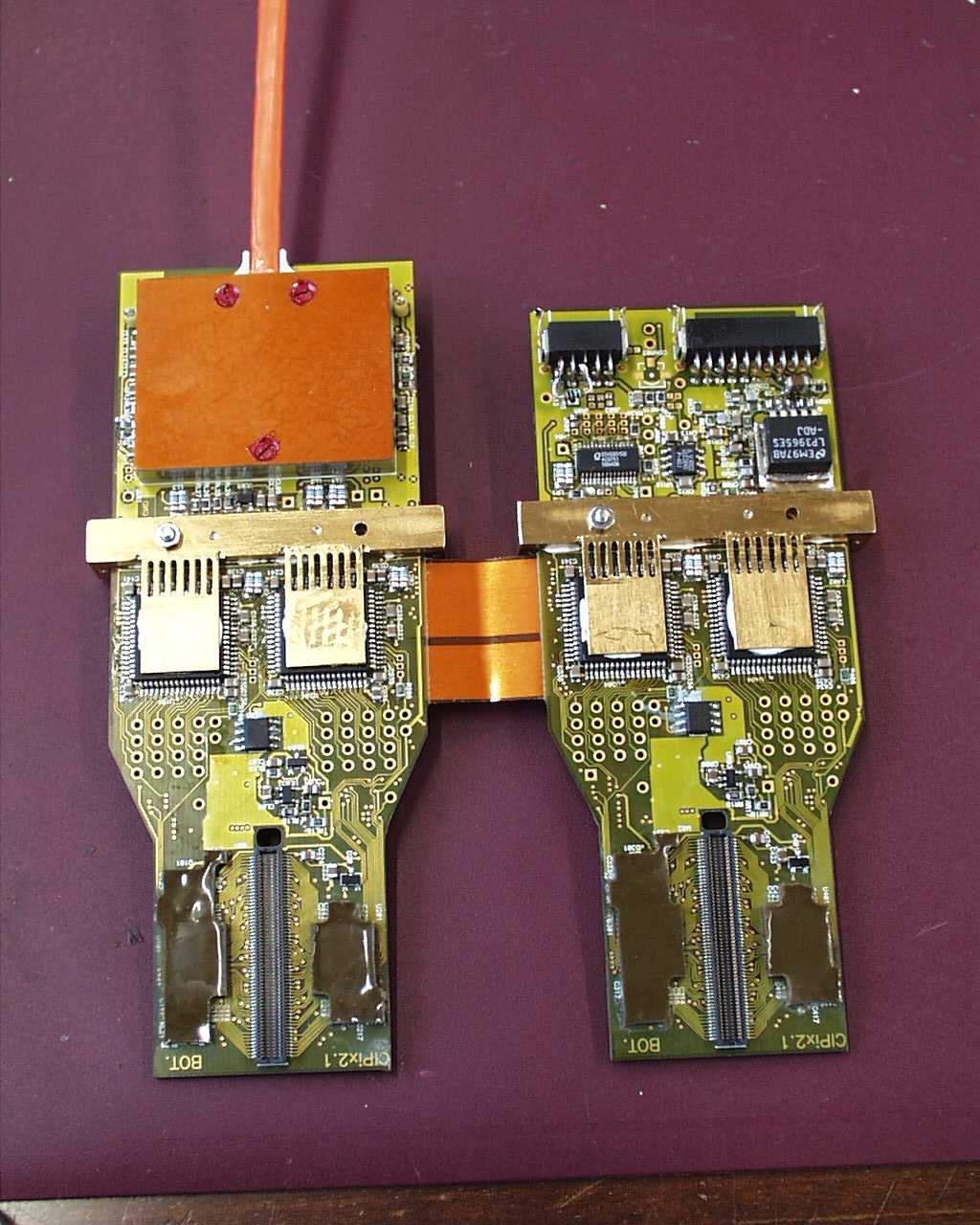
Pair of final CIPIX boards with multi-layer high-speed Kapton bridge.
Chips are covered with epoxy to protect bond wires.
Optical hybrid not yet fully assembled.
|
 small small |
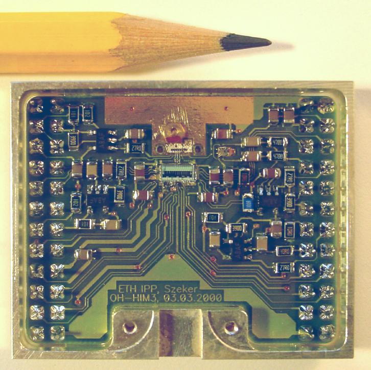
Optical hybrid, chamber side |
 small small |
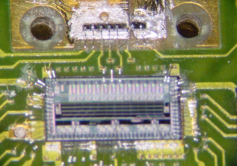
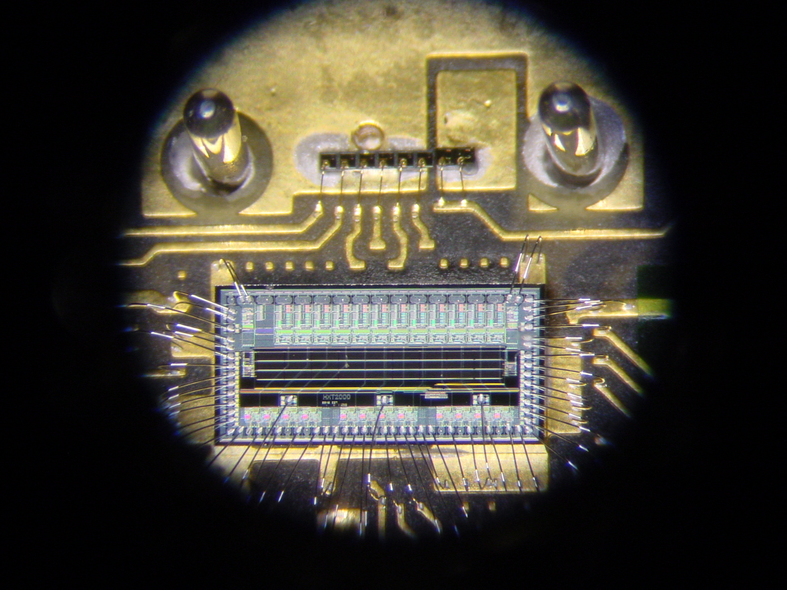
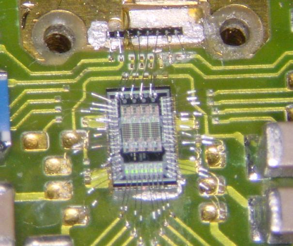
Driver chip |
 small small |
6 GaAs VCSEL vertical cavity surface emitting laser diodes for digital and analog data
and 2 pin diode receivers for clock signals |
 small small |
|
 small small |
|
 |
Optical connector with 8 fibers ending in a 90 degree bend |
 |
Receiver and de-multiplexer schematics |
 small small |
Receiver card |
 small small |
Optical hybrid, receiver end |
 small small |
Receiver chip |
 small small |
receivers between holes for alignment pins |
 small small |
2 VCSELs for clock signals, 6 pin diode receivers |
 small small |
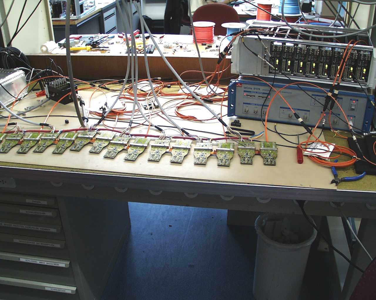
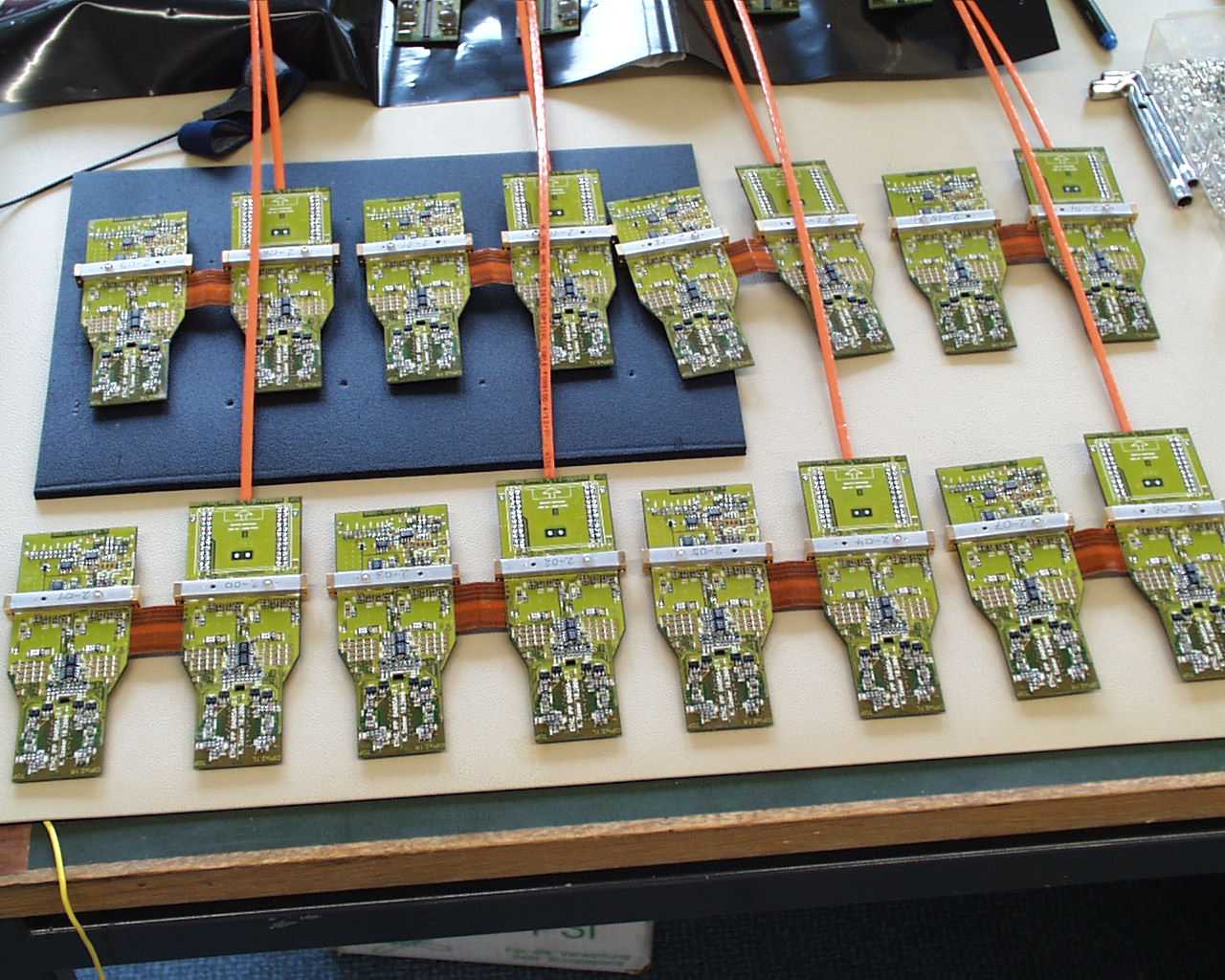
CIPIX board series production |
 small small |
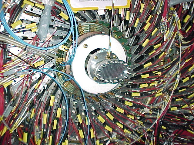
Finished CIP chamber under HV test |
 small small |
|
 small small |
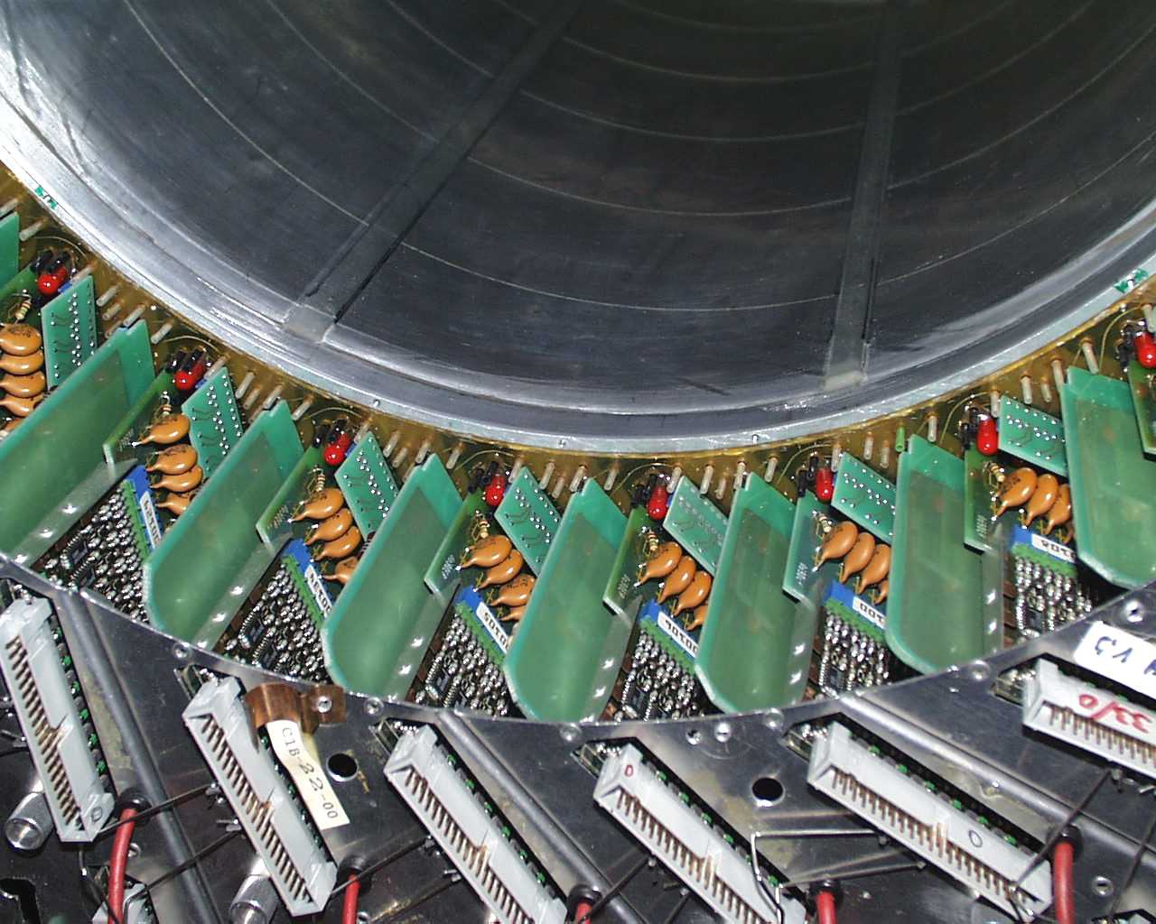
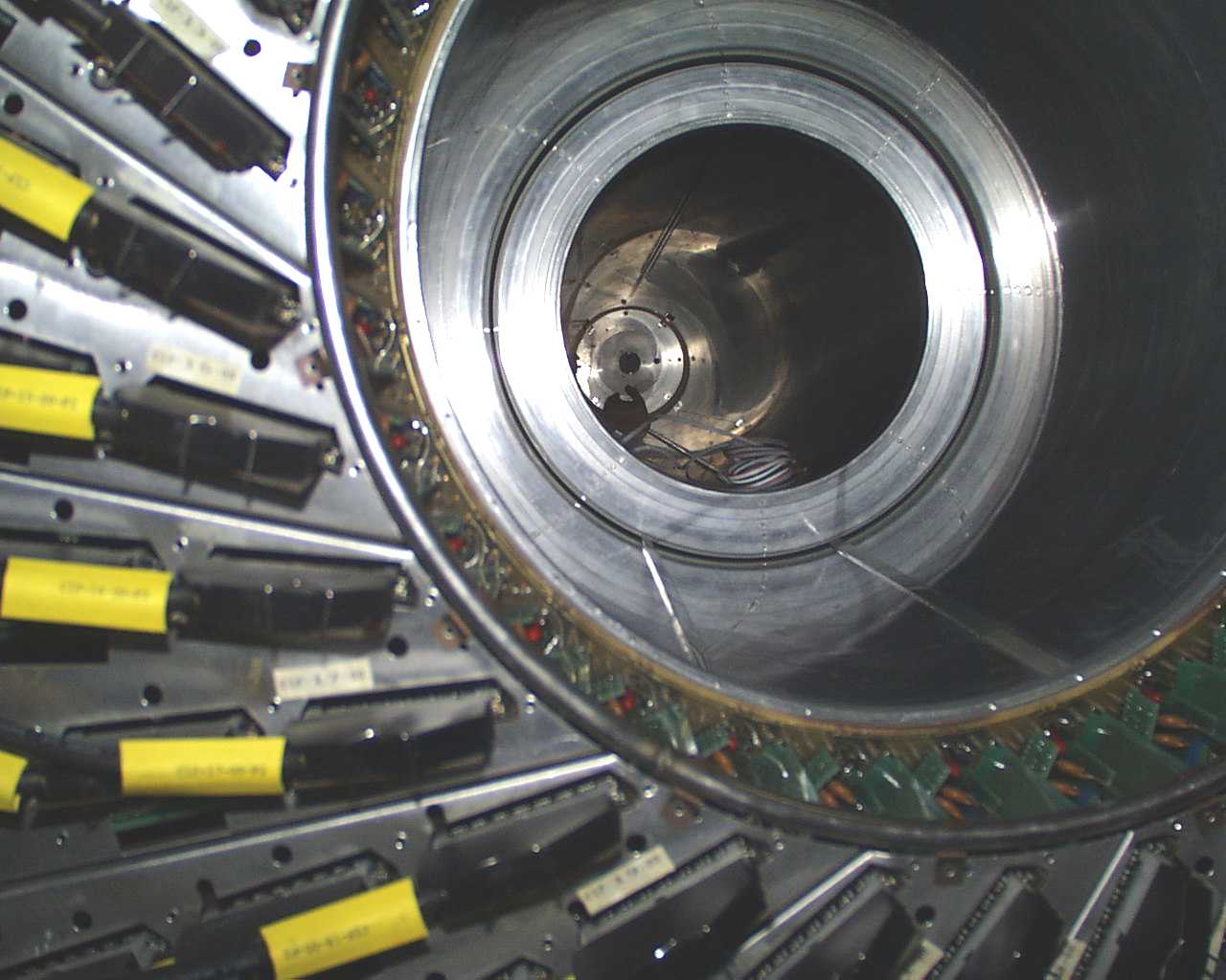
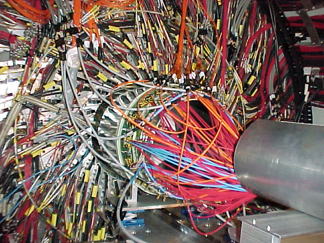
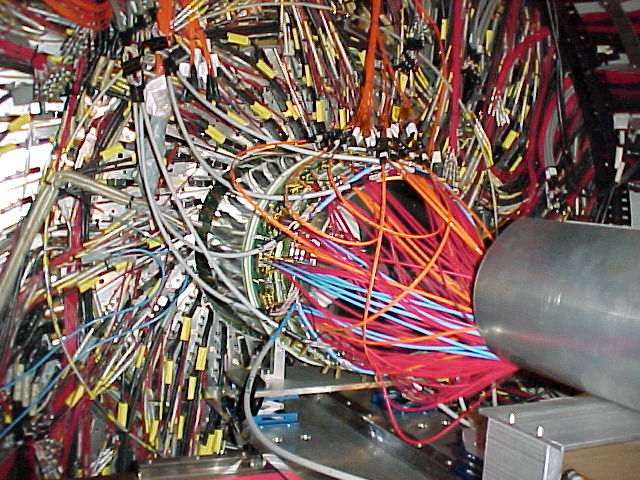
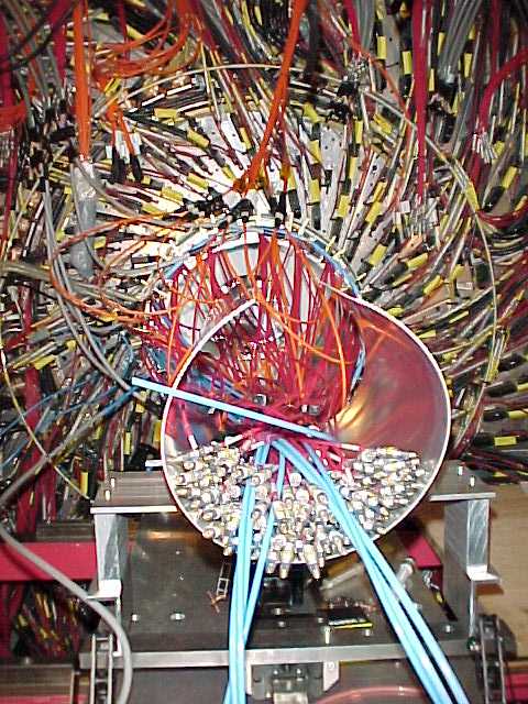
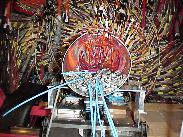
Connectors from pad coax cables to CIPIX cards |
 small small |
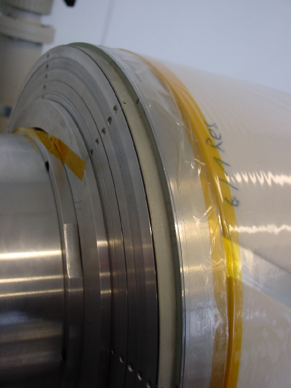
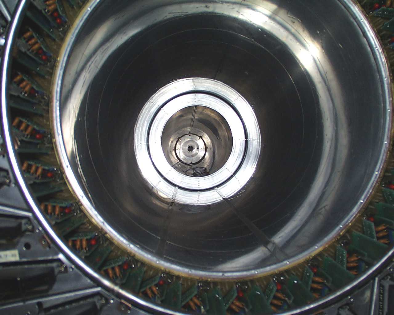
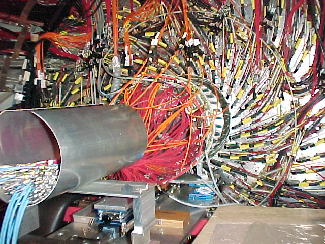
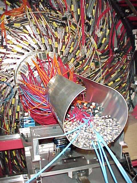
+z end: 5 layers expand freely |
 |
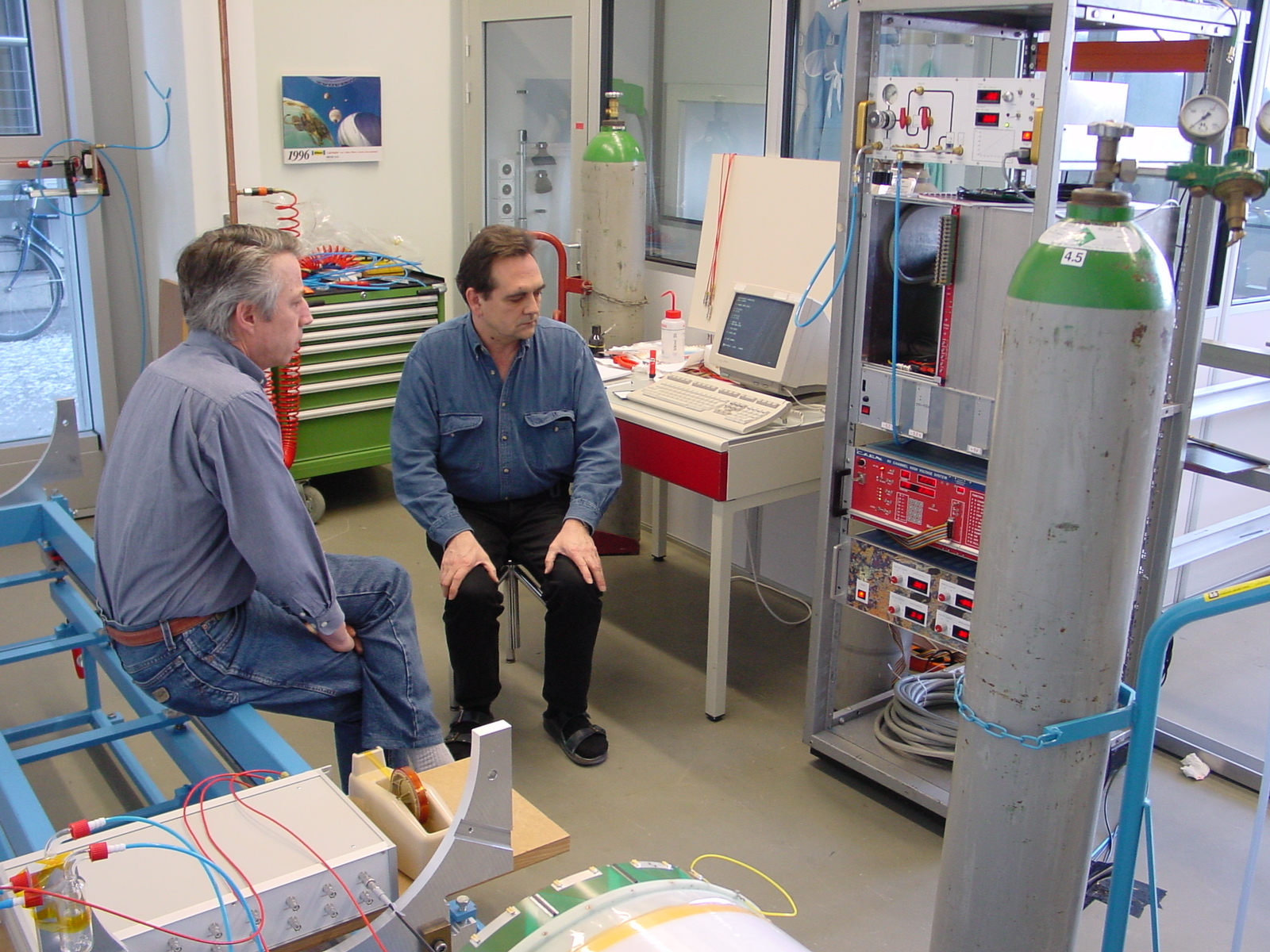
8.2.2001
System test at Zürich with 2 boards in layer 3 |
 |
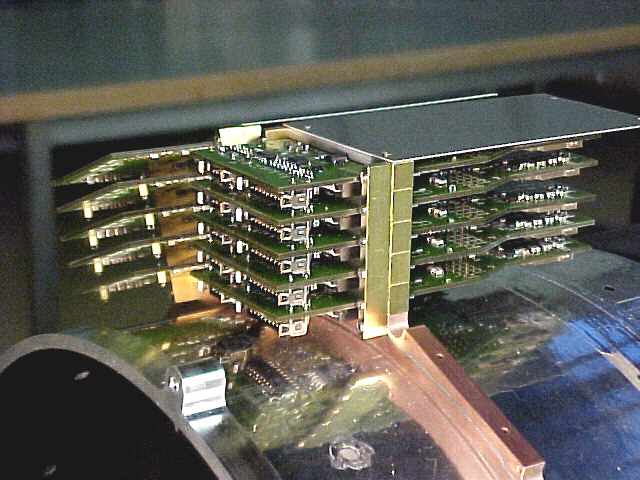
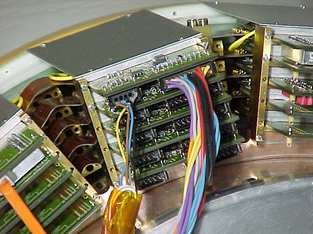
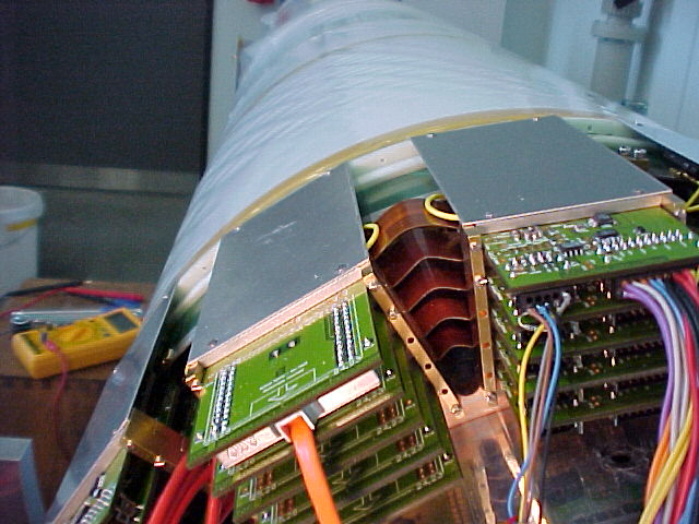
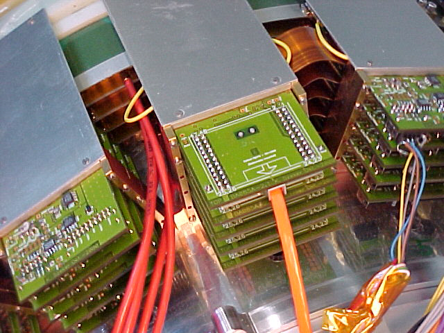
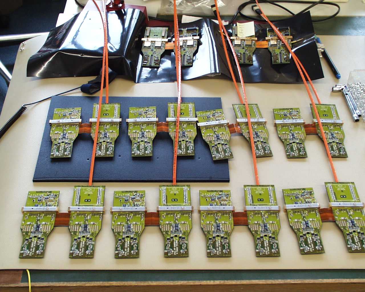
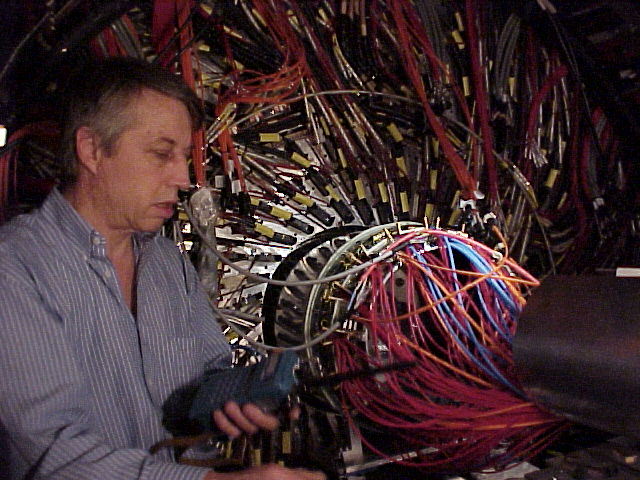
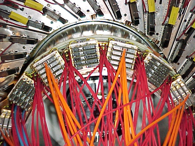
Building 5-layer readout towers
Mechanical test |
 |
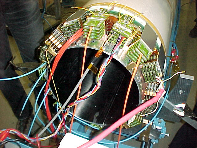
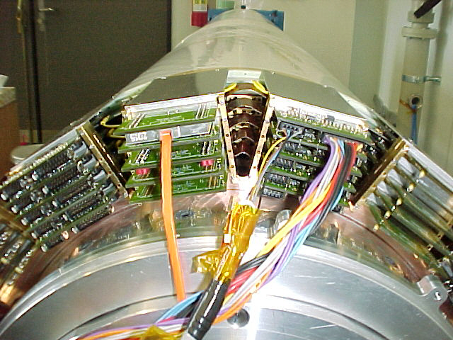
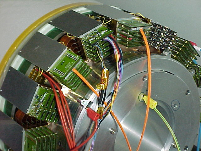
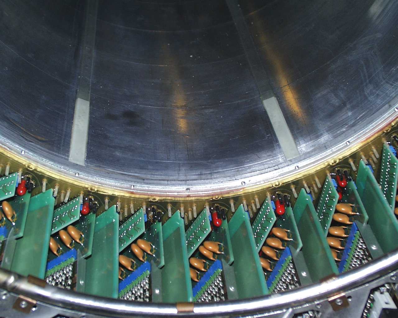
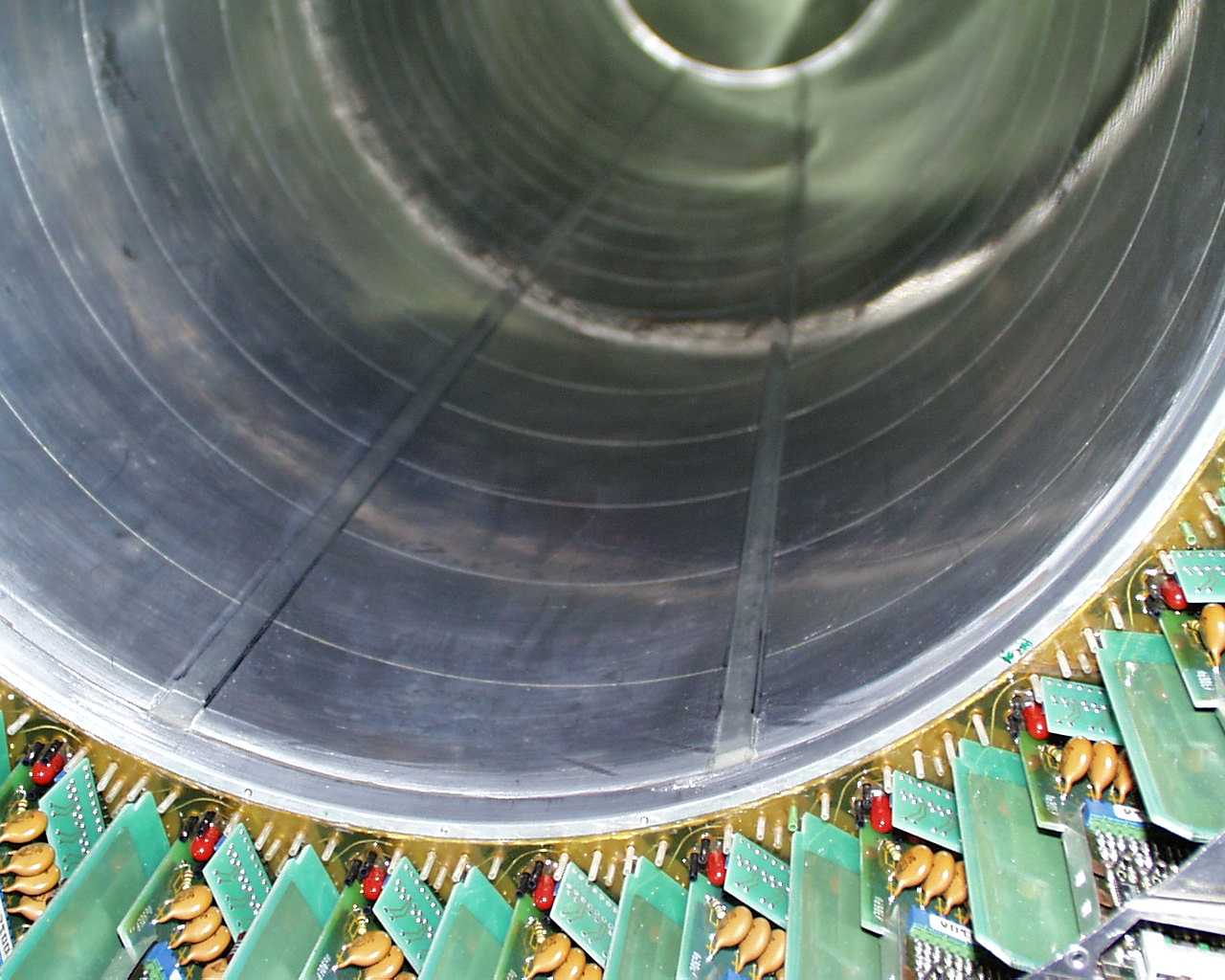
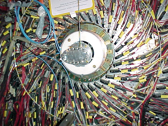
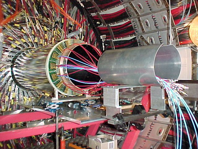
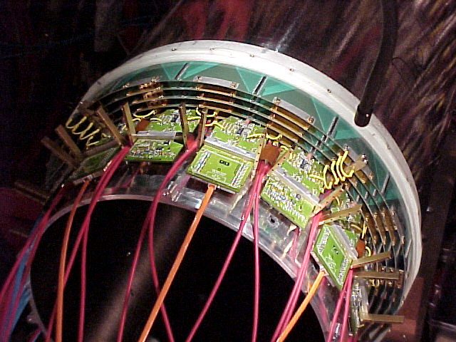
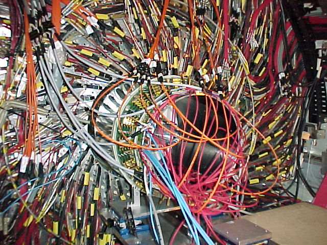
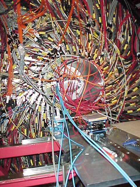
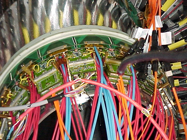
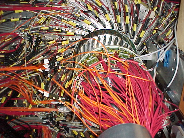
14.2.2001: All 80 boards mounted
with gas and HV cables and 2 CIPIX board pairs fully cabled |
 |
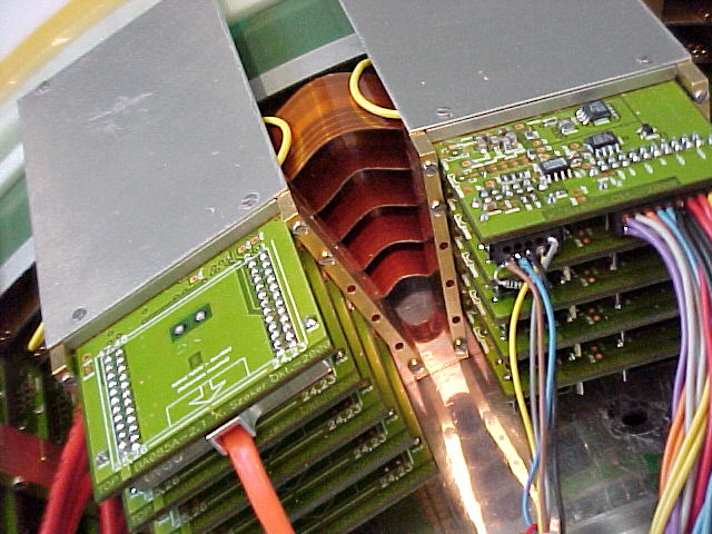
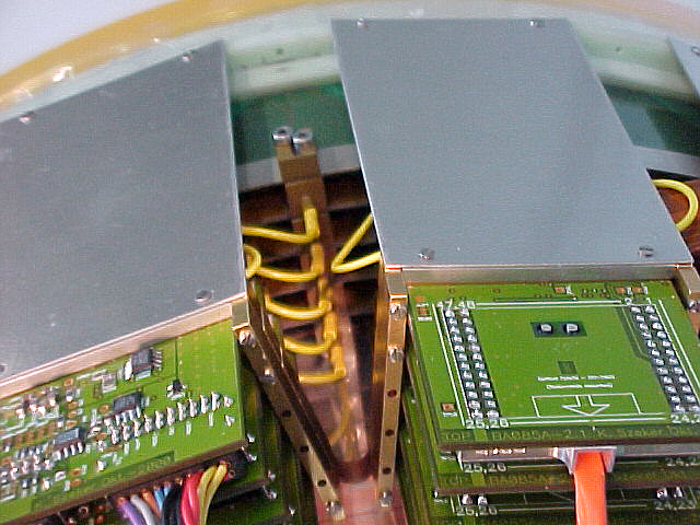
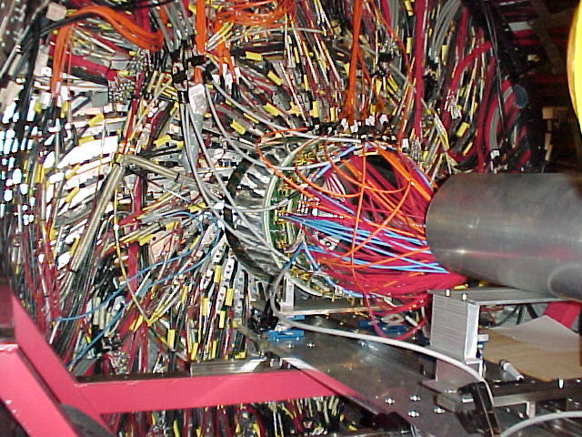
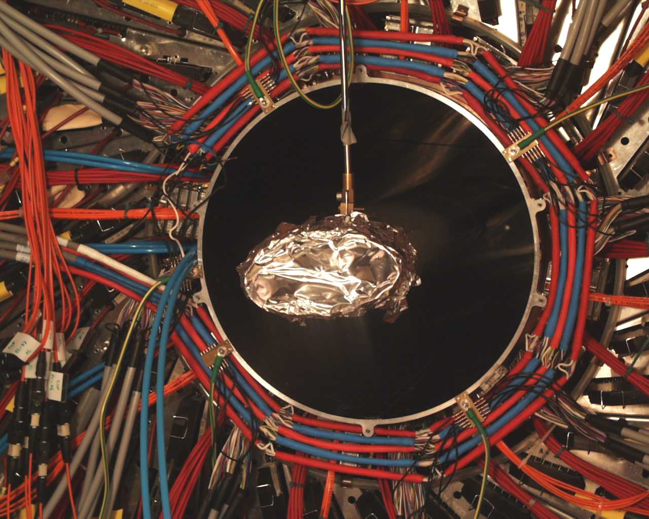
Each pair of CIPIX cards will have an 8-fiber optical cable (orange)
a cable for control signals, and one for the low voltage supply |
 |
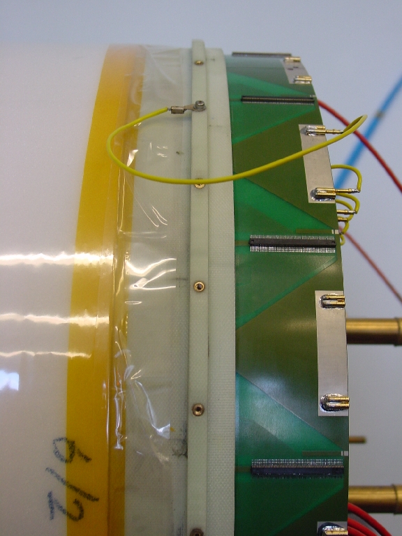
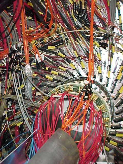
Yellow grounding wires between chamber and frontend board
must be as short as possible |
 |
|
 |
|
 |
|
 |
|
 |
|
 |
|
 |
|
 |
|
 |
|
 small small |
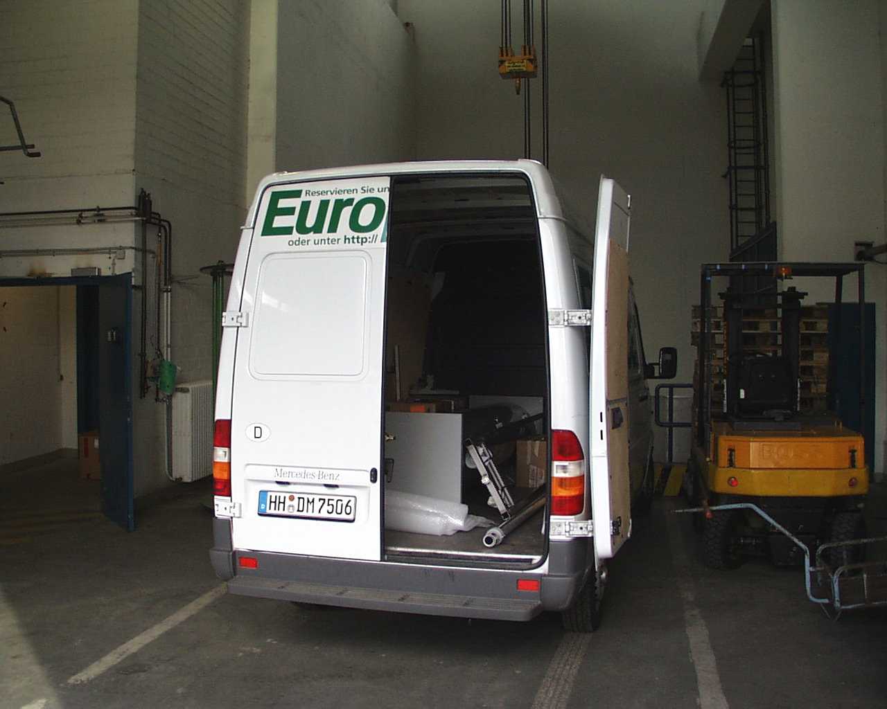
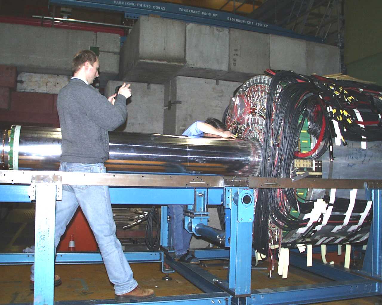
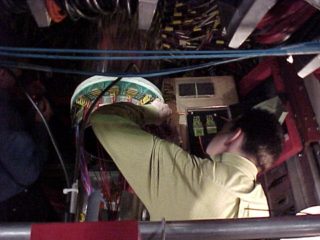
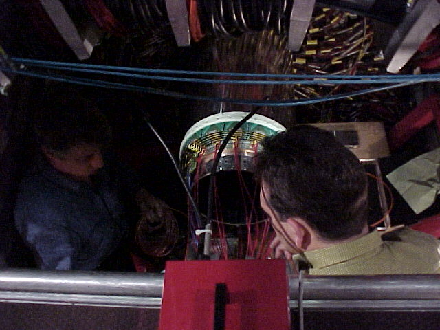
17.2.2001
CIP arrives at DESY |
 small small |
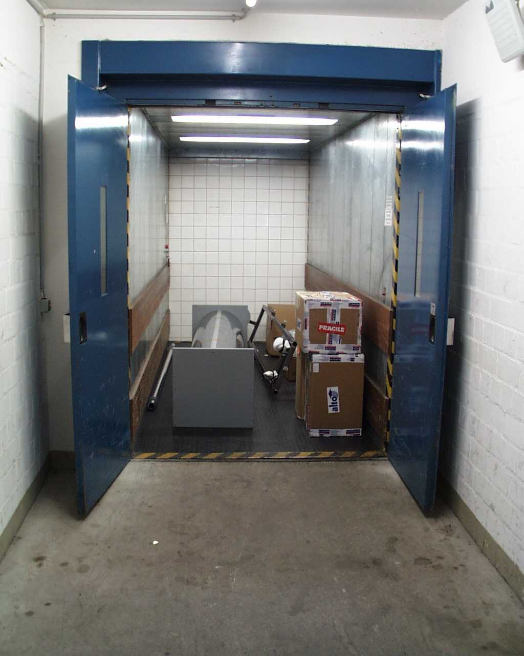
Down the elevator |
 small small |
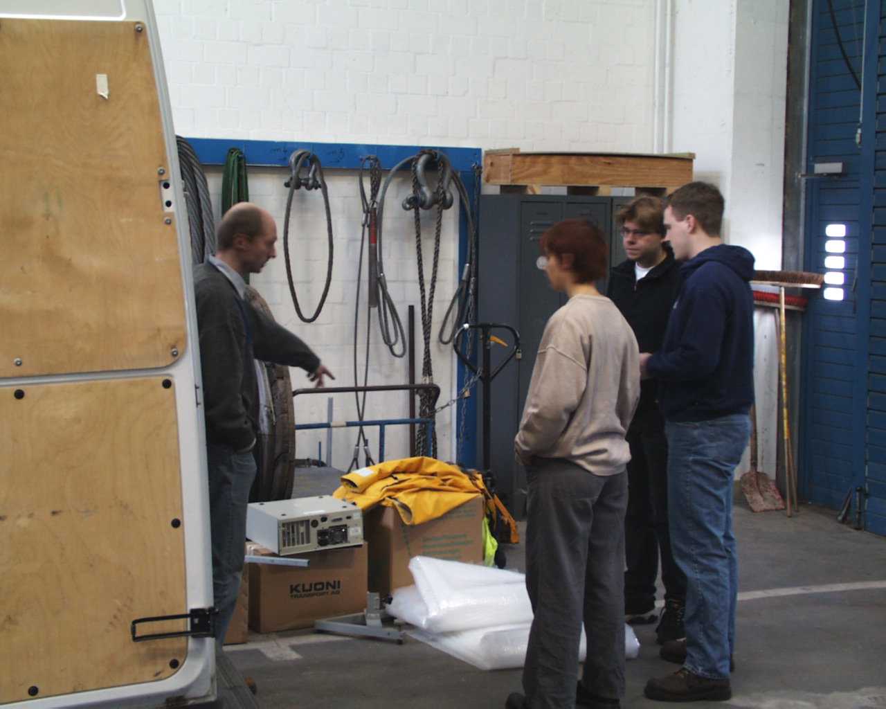
Malte Hildebrandt gives directions for Nicole Werner, Max Urban and
Jan Becker |
 small small |
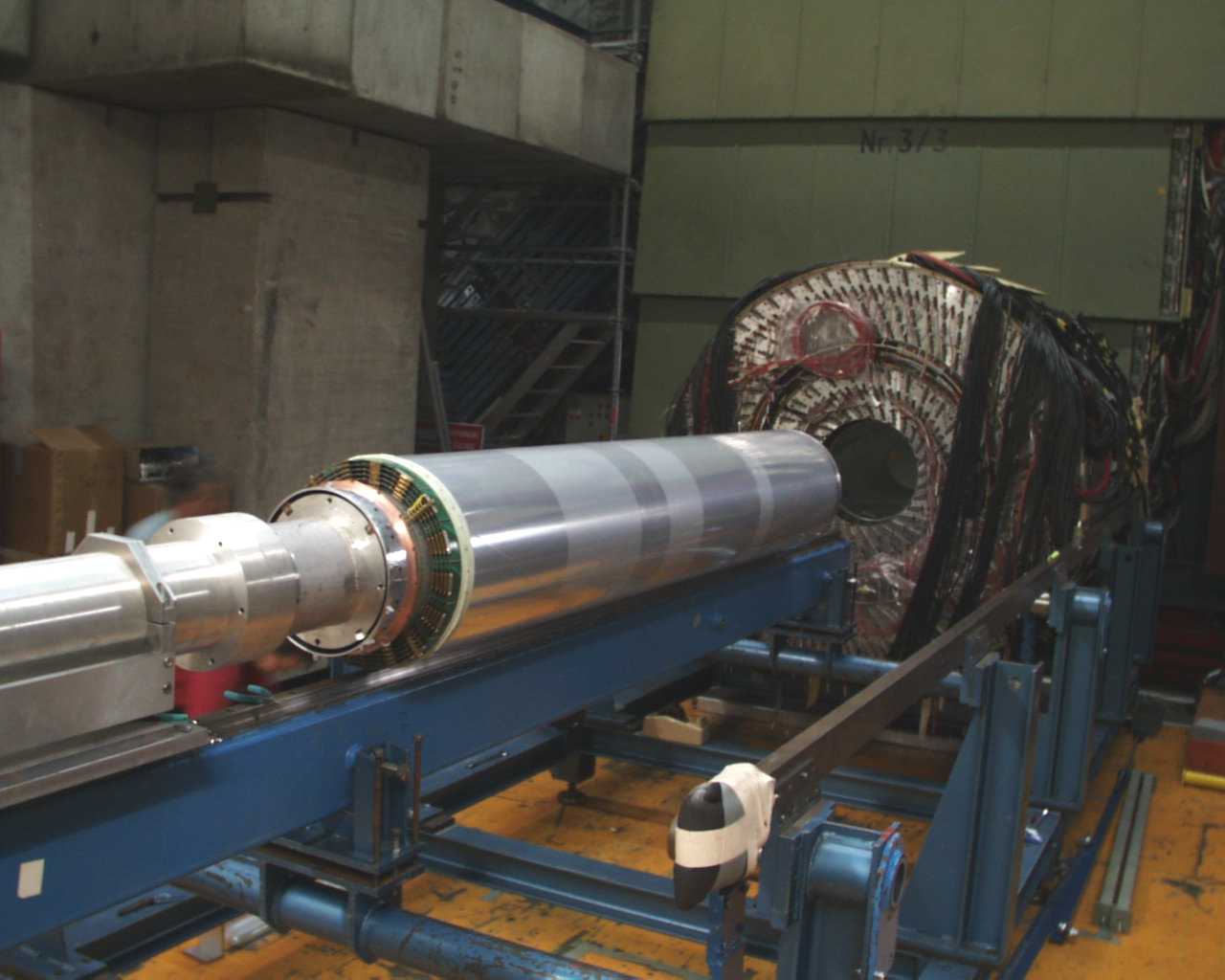
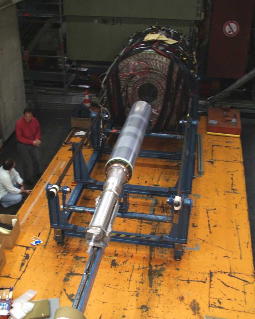
CIP on the installation tool |
 small small |
|
 small small |
|
 small small |
Frontend electronics still to come... |
 small small |
|
 small small |
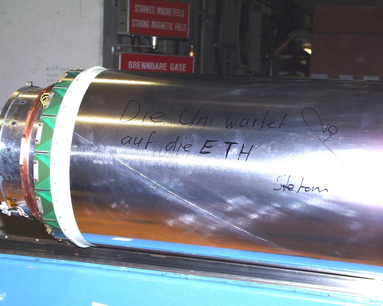
Kurt Bösiger and Stefan Steiner taking documentation |
 small small |
|
 small small |
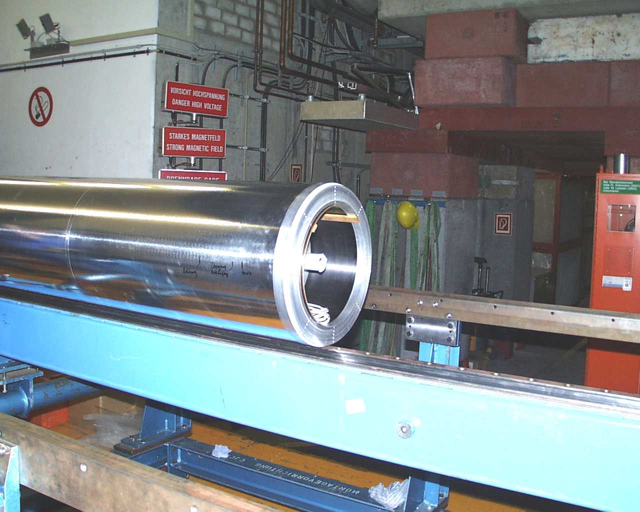
Plexiglass guiding rails glued onto CJC CFK tank
View from +z |
 small small |
|
 small small |
View from -z |
 small small |
|
 small small |
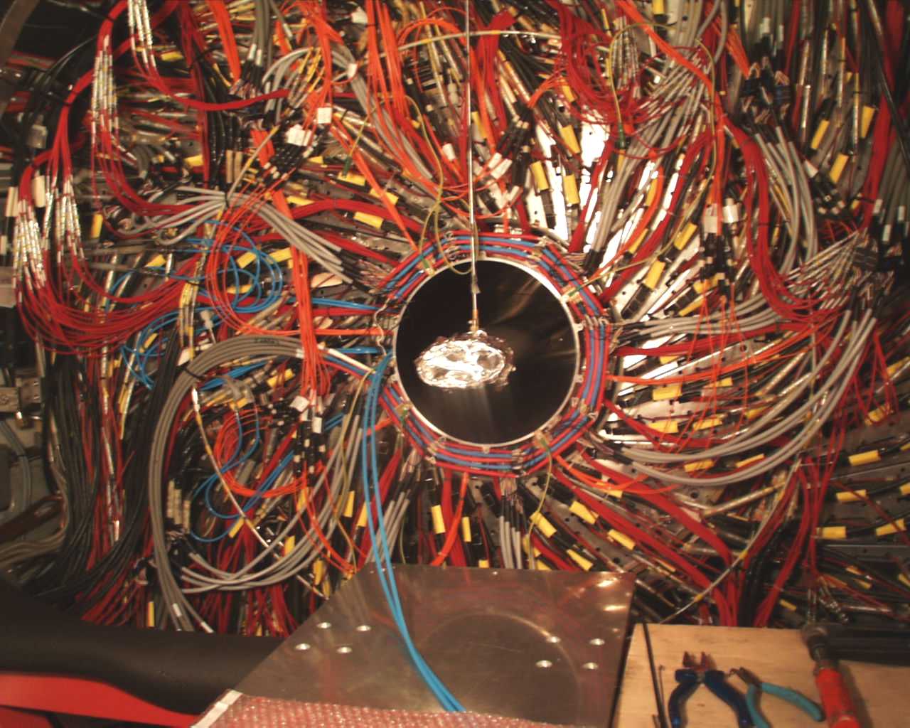
First test installation |
 small small |
Stefan Steiner taking aim |
 small small |
Watching from +z |
 small small |
|
 small small |
Removing the insertion tool |
 small small |
|
 small small |
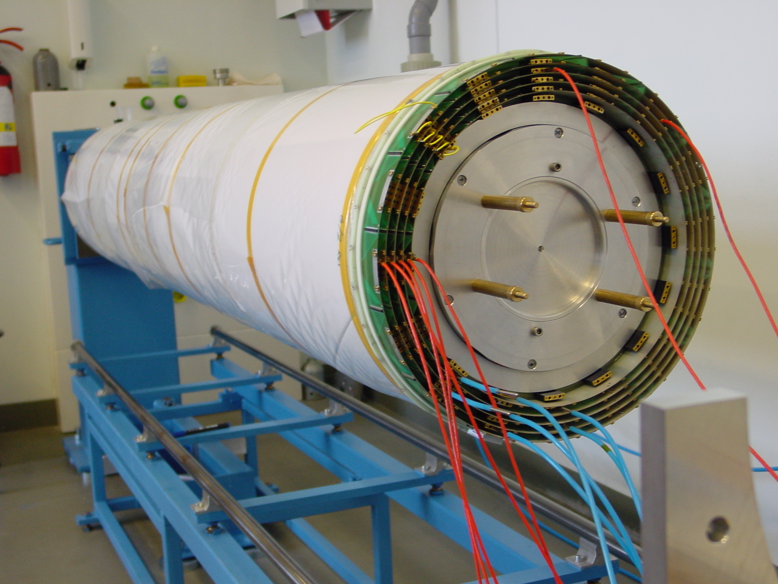
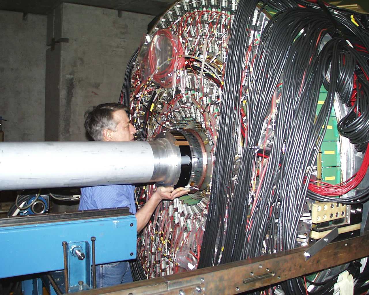
5-layer CIP fully inserted (within 1 mm in z).
Test with FST contact ring was next. Successful |
 small small |
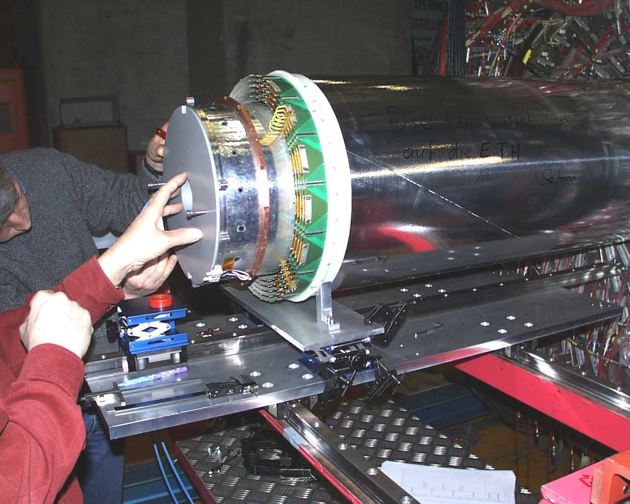
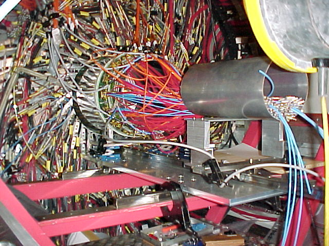
Test of the support for the electronics installation.
Allows full rotation of the chamber. |
 |
|
 half half |
|
 half half |
|
 half half |
|
 half half |
|
 half half |
|
 half half |
|
 half half |
|
 half half |
|
 half half |
|
 half half |
|
 |
|
 |
|
 |
|
 |
|
 |
|
 |
|
 |
|
 |
|
 |
|
 |
|
 |
|
 |
|
 |
|
 |
|
 |
|
 |
|
 |
|
 |
|
 |
|
 |
|
 |
|
 |
|
 |
|
 |
|
 half half |
|
 half half |
|

 small
small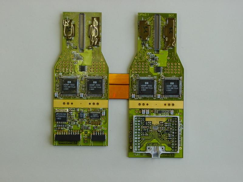
 small
small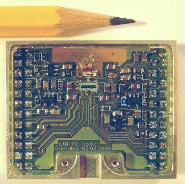
 small
small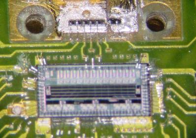
 small
small
 small
small
 small
small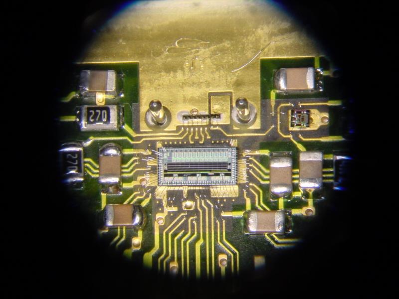
 small
small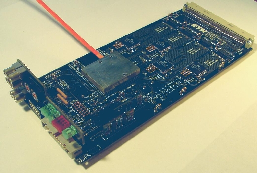
 small
small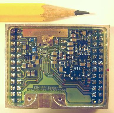
 small
small
 small
small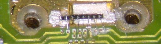
 small
small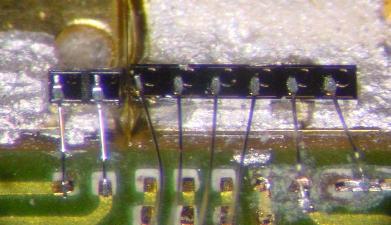
 small
small
 small
small
 small
small
 small
small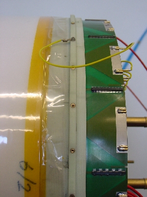
 small
small


 small
small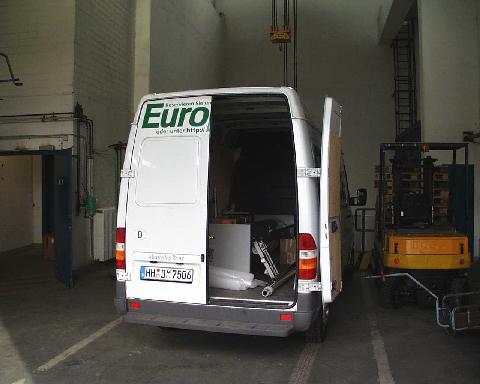
 small
small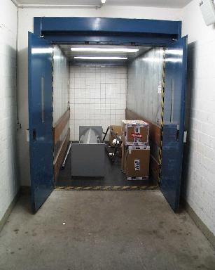
 small
small
 small
small
 small
small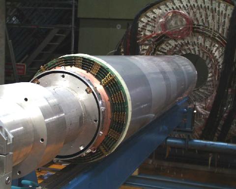
 small
small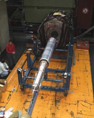
 small
small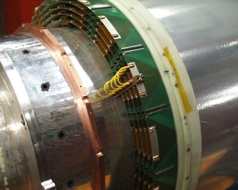
 small
small
 small
small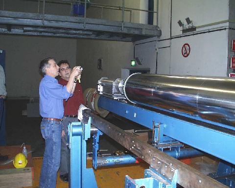
 small
small
 small
small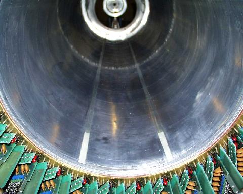
 small
small
 small
small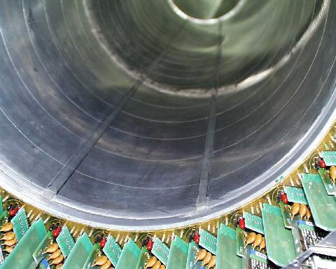
 small
small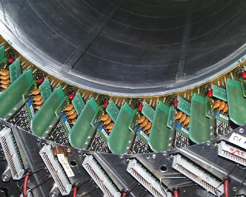
 small
small
 small
small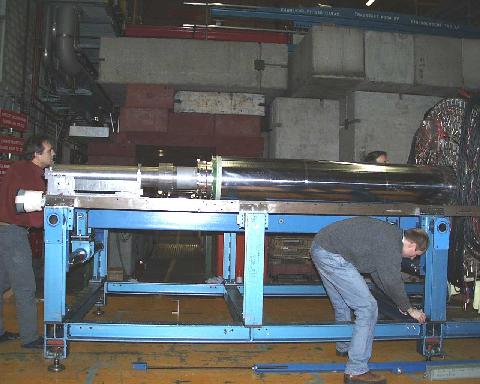
 small
small
 small
small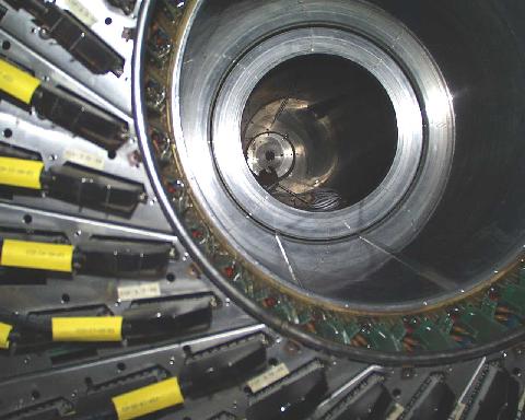
 small
small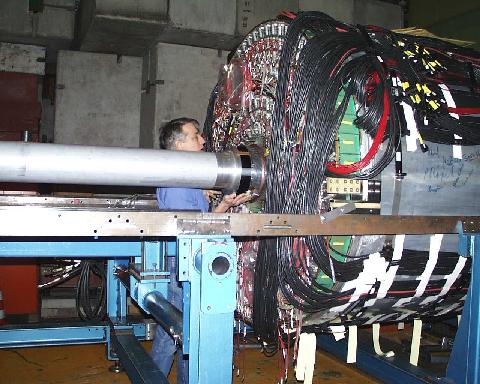
 small
small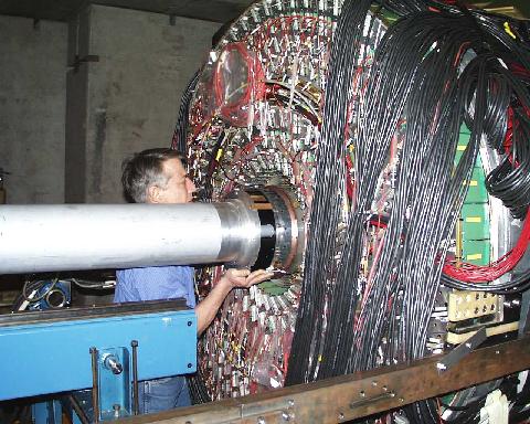
 small
small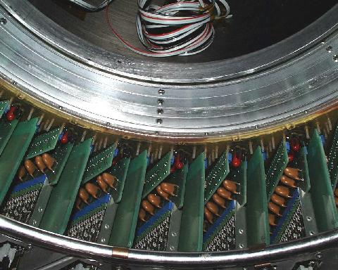
 small
small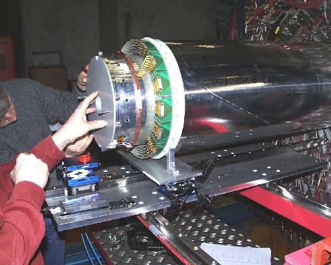
 half
half
 half
half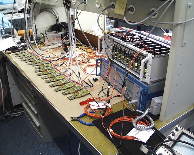
 half
half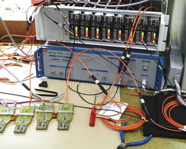
 half
half
 half
half
 half
half
 half
half
 half
half
 half
half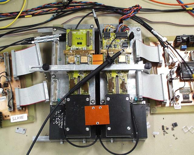
 half
half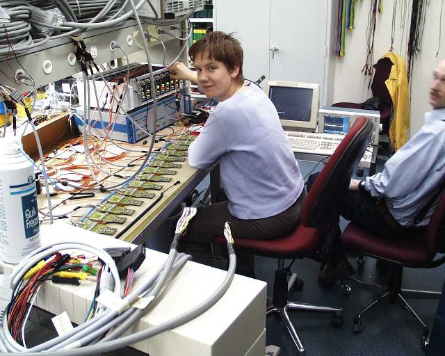


 half
half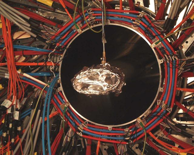
 half
half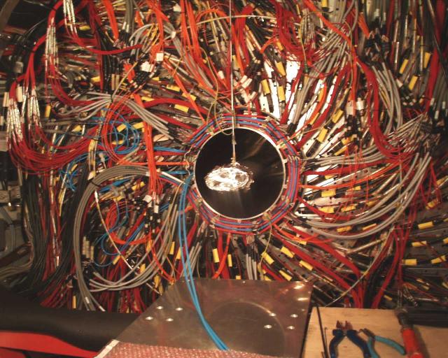