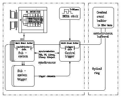
| The detector subsystem data are feed into front end pipelines (multi Event Buffers). They sent fast informations to the individual Subsustem Triggers, where the data are encoced in 256 so called Trigger Elements and send to the central trigger logic. The pipelined first level trigger runs deadtime free at 10.4 MHz and is phase-locked to the RF signal of HERA (HERA-Clock). For each bunch crossing a delayed decision afer 2.5 micro sec.is delivered. Most of the subsystem triggers are able to deliver a trigger element called t_0-bit that indentifies the bunch crossing which triggered the event. Using this bits, the incomming trigger elements are synchronized at the input to the central tigger logic to ensure that only information from the same bunch crossing enters into the trigger decision. | ||
 |
||
|
The system is composed of three logical components as shown in the figure above. The
central trigger provides the decision on acceptance of each event on the basis on the
Trigger Elements set by the individual subdetectors, and to distribute the synchronized
timing signals that control hte the subsystem readout such that data in the pipelines
are properly assigned to the correct bunch crossing. The decison on aceptance, the L1 Keep signal, of an event is made on the basis of 128 logical combinations of the 256 trigger elements, called subtriggers. Every subtrigger condition must contain at least one t_0 bit that allow to uniquely assign the correct bunch crossing. The pipelines are then held an deadtime starts to accumulate. The data acqusiton proceeds in severl stages, partly in paralell. The L1-keep is validated by the subsequent level of the trigger (L2/L3/L4). The L1 Keep signals closes the pipelines and dead time starts. After the L2 verification, the L2 Keep signal, the readout is initalized. After all buffers are read out (FER ready ), the pipelines are cleared (Fast Clear) and reopened again ( Timing Sequence). |
||